Converter apparatus, inverter apparatus, and DC link voltage control method

a technology of inverter and converter, which is applied in the direction of motor/generator/converter stopper, dynamo-electric converter control, and dynamo-electric gear control. it can solve the problems of poor reuse efficiency, unfavorable dc link voltage increase, and poor reuse efficiency. , to achieve the effect of increasing the reusable regenerative energy

a technology of inverter and converter, which is applied in the direction of motor/generator/converter stopper, dynamo-electric converter control, and dynamo-electric gear control. it can solve the problems of poor reuse efficiency, unfavorable dc link voltage increase, and poor reuse efficiency. , to achieve the effect of increasing the reusable regenerative energy

US20060033466A1Active Publication Date: 2006-02-16FANUC LTD

Image

  • Converter apparatus, inverter apparatus, and DC link voltage control method
  • Converter apparatus, inverter apparatus, and DC link voltage control method
  • Converter apparatus, inverter apparatus, and DC link voltage control method

Examples


first embodiment

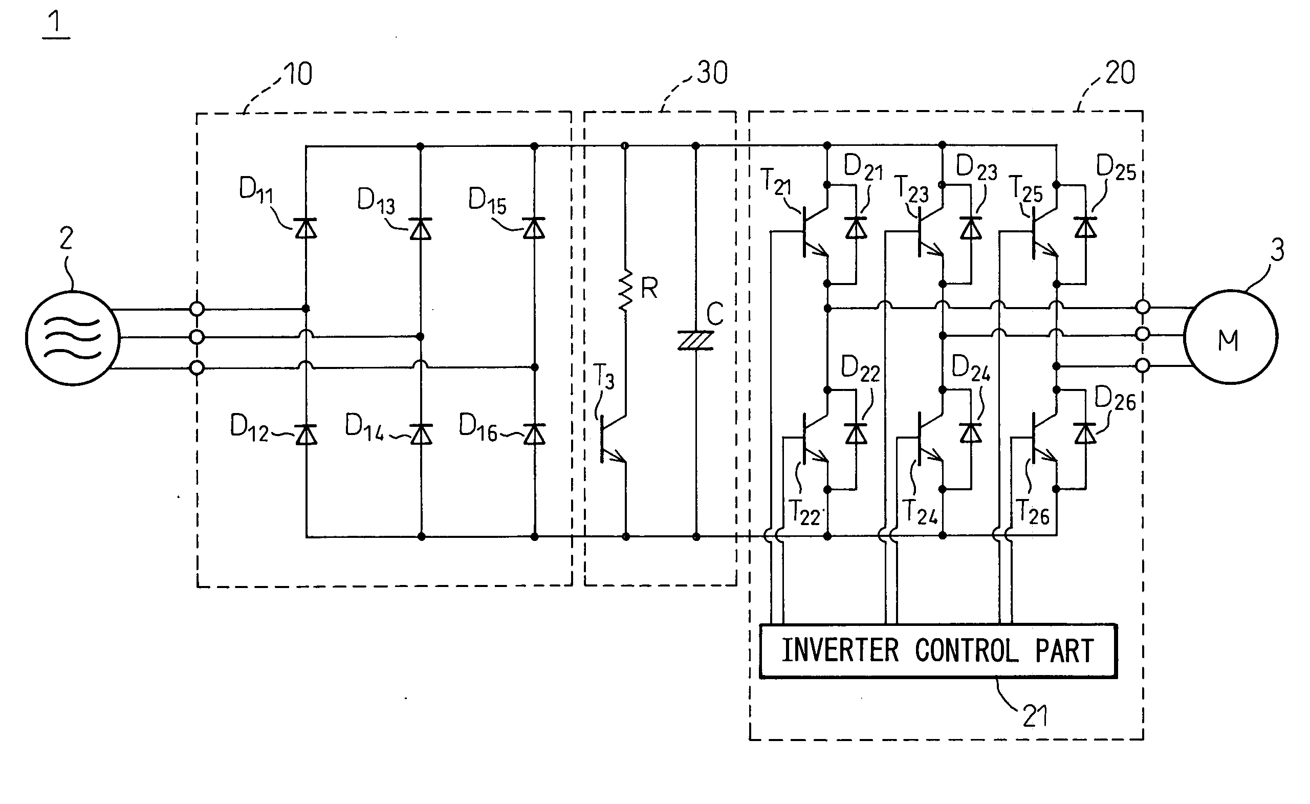
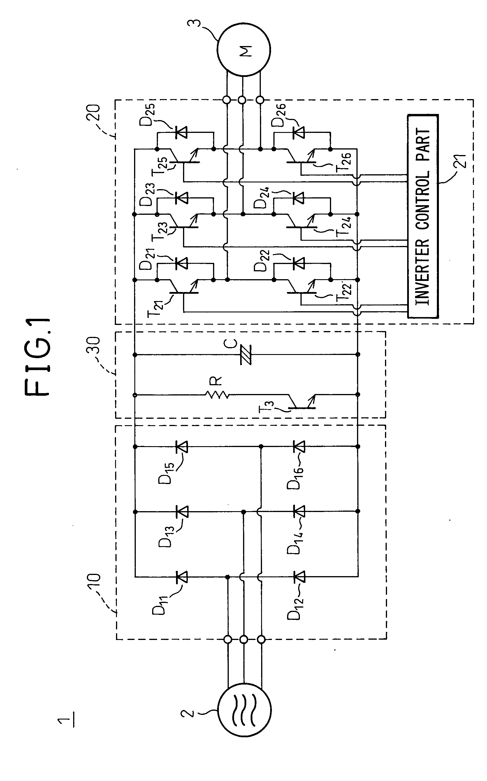
[0028] Preferred embodiments of the present invention will be described in detail below with reference to the accompanying drawings. FIG. 2 is a diagram schematically showing the configuration of a converter apparatus according to the present invention and an inverter apparatus according to the embodiment of the present invention that comprises the converter apparatus.

[0029] As shown, the inverter apparatus 1 comprises: the converter apparatus 10, connected to a three-phase commercial power source 2 via reactance 4, for converting the supplied power into DC power; an inverter circuit 20 for converting the DC power into variable-voltage variable-frequency AC power for supply to a motor 3; and a DC link 30 connected between the converter apparatus 10 and the inverter circuit 20 for transmitting the DC power, converted by the converter apparatus 10, to the inverter circuit 20.

[0030] The converter apparatus 10 comprises: a bridge circuit constructed from power devices (for example, tra...

second embodiment

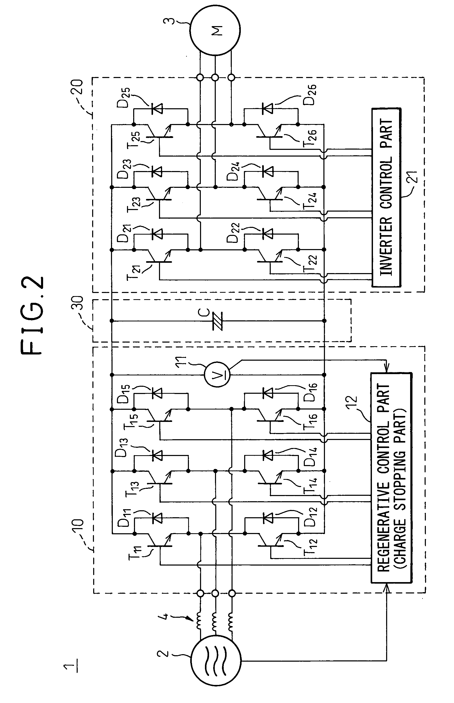
[0044]FIG. 4 is a diagram schematically showing the configuration of a converter apparatus according to the present invention and an inverter apparatus according to the embodiment of the present invention that comprises the converter apparatus.

[0045] In the present embodiment, the DC link voltage Vd appearing when the power storage part C begins to store the regenerative power from the motor 3 (that is, when the motor 3 begins to decelerate) is detected and the detected voltage value is stored; then, with reference to the thus detected voltage, the upper limit voltage of the DC link voltage is determined by adding a predetermined potential difference ΔV1 to the stored value of DC link voltage Vd and, when this upper limit voltage is exceeded, the regenerative control part 12 begins to feed the regenerative power back into the power source.

[0046] For this purpose, the inverter apparatus 10 includes a voltage value storing part 13 for storing the value of the DC link voltage Vd detec...


PUM


Abstract

The invention is directed to the provision of a converter apparatus, an inverter apparatus, and a DC link voltage control method, wherein the upper limit value of the DC link voltage that rises due to regenerative energy occurring from a motor is set high, thereby increasing the regenerative energy to be stored in a DC link. The converter apparatus (10) comprises: a voltage detection part (11) for monitoring the DC link voltage occurring across the DC link (30); and a charge stopping part (12) for stopping charging a power storage part (C) when the detected value of the DC link voltage exceeds a predetermined upper limit voltage as the motor (3) is decelerated.

Description

BACKGROUND OF THE INVENTION [0001] 1. Field of the Invention [0002] The present invention relates to a converter apparatus that converts AC power supplied from a power source into DC power and supplies the DC power to an inverter to drive a motor, and an inverter apparatus that drives a motor by being supplied with power from such a converter apparatus. More particularly, the invention relates to a method for controlling the DC link voltage appearing across a DC link connected between such a converter apparatus and inverter apparatus, and a converter apparatus and inverter apparatus that can control such a DC link voltage. [0003] 2. Description of the Related Art [0004]FIG. 1 is a diagram showing the configuration of a prior art inverter apparatus for controlling the speed of a motor. The inverter apparatus 1 comprises: a converter apparatus 10 for converting AC power supplied from a three-phase commercial power source 2 into DC power; an inverter circuit 20 for converting the DC po...

Claims


Application Information

Patent Timeline
16 Feb 2006
Publication
US20060033466A1
IPC
H02P7/42; H02P27/00; H02M7/48; H02M7/797; H02P3/18; H02P21/36; H02P25/22; H02P27/06
CPC
H02P23/06; H02M5/4585
Inventors
YAMADA, YUUICHI; HANYU, SHIGEKI