Method and apparatus for charging batteries

a battery and charging device technology, applied in the field of battery charging, can solve the problems of not optimally charging batteries, not being able to provide a unique charging current or voltage for each battery, and being unsuitable for battery charging

Active Publication Date: 2006-02-16
ILLINOIS TOOL WORKS INC
View PDF7 Cites 50 Cited by
  • Summary
  • Abstract
  • Description
  • Claims
  • Application Information

AI Technical Summary

Problems solved by technology

Of course, dedicated battery chargers are not versatile, and can require a facility to have a number of chargers.
These chargers might work for any battery of a given voltage, but do not optimally charge batteries.
Thus, if such chargers are used to charge several batteries simultaneously, they cannot provide a unique charging current or voltage for each battery.
This also diminishes the usefulness of chargers.
Some battery chargers are inefficient because they have a poor power factor.
This causes increased costs when power is utility power, and can lessen the charging capacity, particularly when using generator power.
The use of generator power can cause another problem—generators often provide “dirty” power, i.e., power that is not perfectly sinusoidal, or not of a constant value.
Dirty power can result in improper charging.
Often, a user finds the battery is no longer chargeable by charging it, then using it, and having the battery become discharged in a short period of time.

Method used


Image

  • Method and apparatus for charging batteries
  • Method and apparatus for charging batteries
  • Method and apparatus for charging batteries

Examples


Embodiment Construction

[0029] While the present invention will be illustrated with reference to a particular battery charger and particular circuitry, it should be understood at the outset that the invention may also be implemented with other circuitry, software and arrangements.

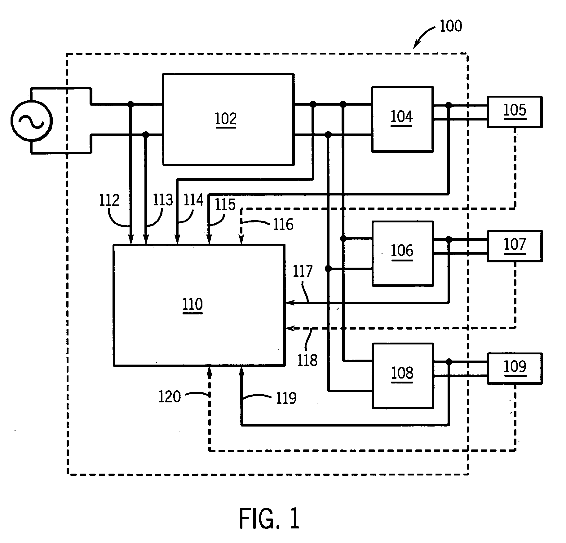
[0030] Generally, the invention is implemented by a battery charger that receives an input, such as an ac input, and provides a dc charging output. Preferably, the battery charger may receive any input over a range of inputs without being reconfigured (i.e., re-linked or re-wired), and may be capable of receiving “dirty” power, such as that from a generator. Also, the battery charger preferably includes an output stage that can either provide a number of voltages for charging different batteries, any voltage, or be designed for a single voltage. There can be a plurality of user-removable output stages. When the output circuits provides a single voltage, or a narrow range of voltages for charging one battery voltage, it is said to...


PUM


Abstract

A method and apparatus for charging batteries includes using an input rectifier to receive an ac input and provide a dc signal. A converter receives the dc signal and provides a converter output. An output circuit receives the converter output and provides a battery charging signal. A controller preferably controls the converter to power factor correct. The system can include multiple output circuits, used either singly or at the same time, and designed for one or more voltages. They can be user removable. Preferably, the converter output has a magnitude independent of a range of frequencies and a range of magnitudes of the ac input, and the range can be, for example, at least a factor of two or at least two utility voltages. The controller includes a charging schedule module that receives feedback, such as voltage and / or current feedback and / or temperature feedback. The output circuit, such as a dc-dc converter, is controlled in response to the feedback in other embodiments. The battery type may be sensed or input by a user, and the charging done in response to the battery type. A defective battery sensor is preferably included, with a user-noticeable indicator.

Description

FIELD OF THE INVENTION [0001] The present invention relates generally to the art of battery charging. More specifically, it relates to battery charging using versatile circuitry that can preferably receive multiple inputs and / or provide multiple outputs. BACKGROUND OF THE INVENTION [0002] There are a large number of rechargeable batteries having a wide variety of voltages and charging schedules. (Charging schedule, as used herein, is the manner in which the charging is performed for a given battery. For example, one charging schedule might call for a limited amount of current initially, and then a greater current when the battery voltage crosses a threshold, followed by a trickle charge after the battery voltage crosses a second threshold.) It is typical that a charger be designed for a single battery type, and have a single output voltage and charging schedule. Of course, dedicated battery chargers are not versatile, and can require a facility to have a number of chargers. [0003] O...

Claims


Application Information

Patent Timeline
Patent Type & Authority Applications(United States)
IPC IPC(8): H02J7/00
CPCH02J7/0018H02M2001/008H02M2001/007H02J7/022H02J7/02H02J2207/20H02M1/007H02M1/008
Inventor STANZEL, DAVID A.REYNOLDS, JON O.
Owner ILLINOIS TOOL WORKS INC
Why Eureka
Try Eureka