

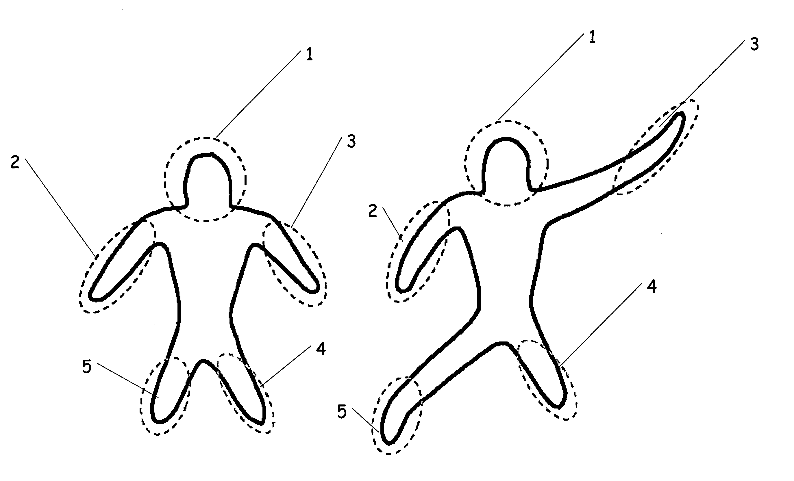
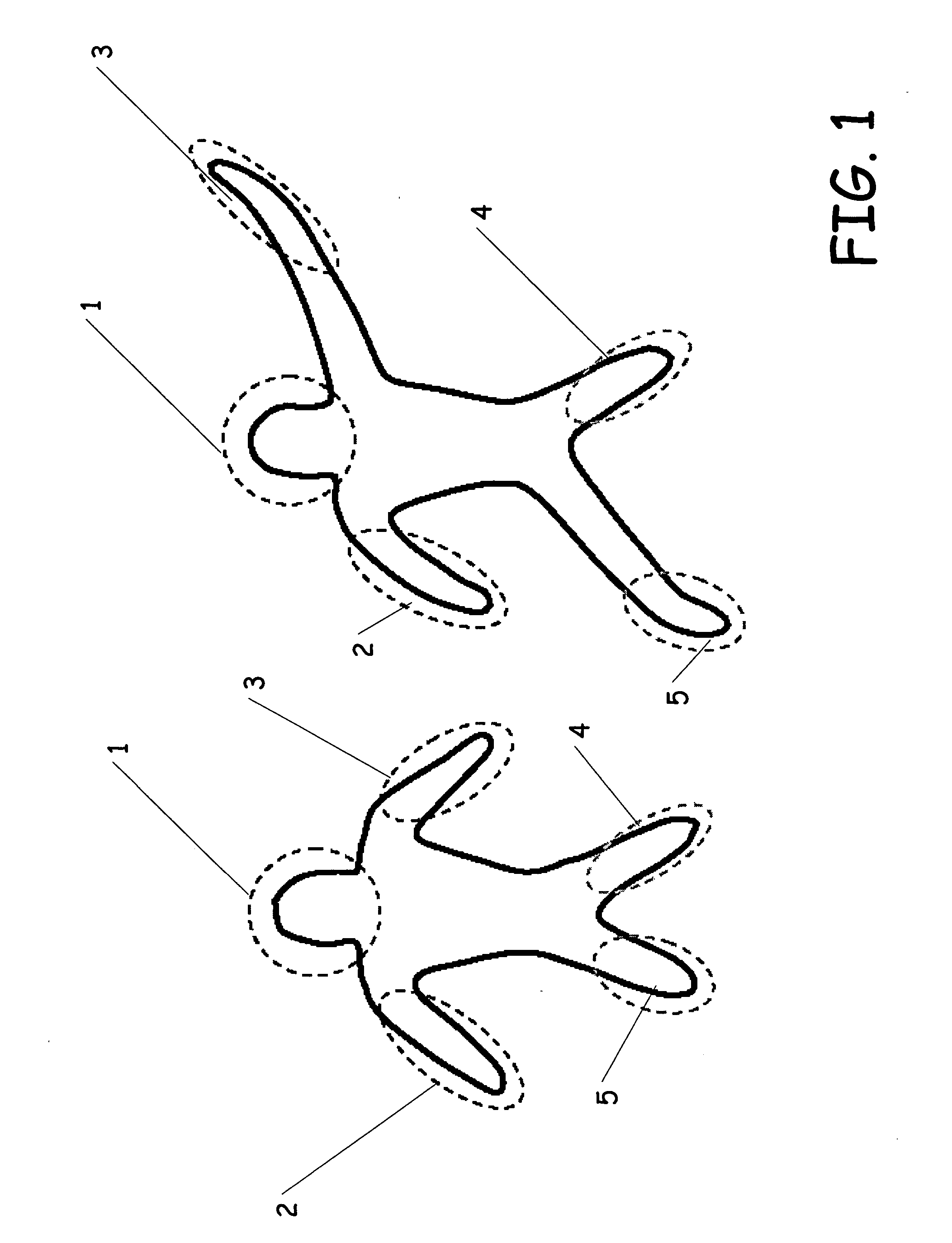
Perceptually based approach for planar shape morphing
a perception-based approach and planar shape technology, applied in the field of computer generated graphics, can solve the problems of ineffective computation of features used in their methods, inability to effectively compute features, and inability to shrink or contain intermediate shapes, etc., and achieve the effect of reducing costs
- Summary
- Abstract
- Description
- Claims
- Application Information
AI Technical Summary
Benefits of technology
Problems solved by technology
Method used
Image

Examples
Embodiment Construction
[0032] The present invention involves morphing between shapes. However, before describing the present invention in more detail, one illustrative environment in which the present invention can be used will be discussed.
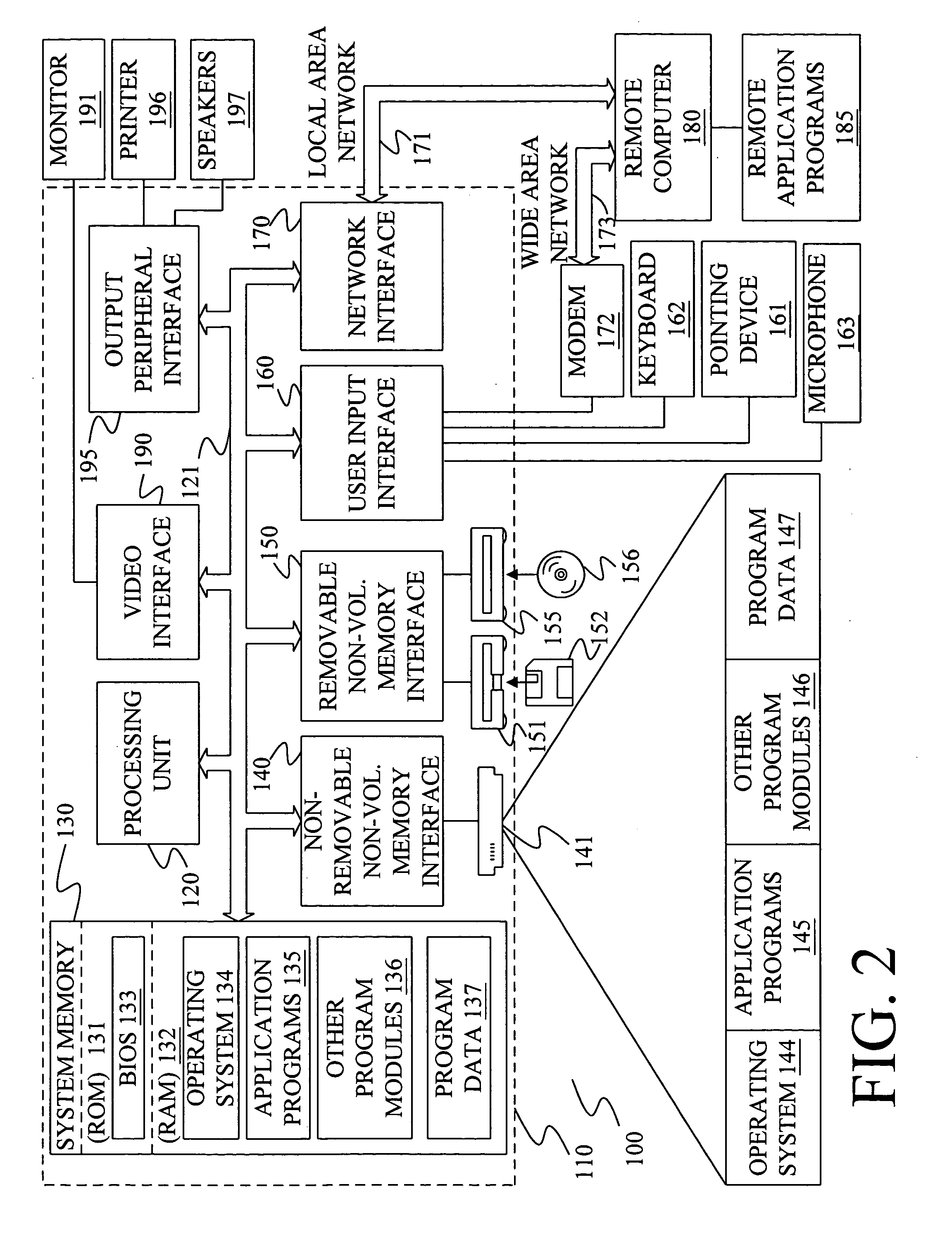
[0033]FIG. 2 illustrates an example of a suitable computing system environment 100 on which the invention may be implemented. The computing system environment 100 is only one example of a suitable computing environment and is not intended to suggest any limitation as to the scope of use or functionality of the invention. Neither should the computing environment 100 be interpreted as having any dependency or requirement relating to any one or combination of components illustrated in the exemplary operating environment 100.
[0034] The invention is operational with numerous other general purpose or special purpose computing system environments or configurations. Examples of well known computing systems, environments, and / or configurations that may be suitable for use with...
PUM
 Abstract
Description
Claims
Application Information