
Exposure apparatus and exposing method

a technology which is applied in the field of exposing apparatus and exposing method, can solve the problems of reducing the life of the exposing mask, reducing the accuracy of attaching/detaching, and naturally oscillating the exposing mask

Inactive Publication Date: 2006-02-16
CANON KK
View PDF8 Cites 13 Cited by
  • Summary
  • Abstract
  • Description
  • Claims
  • Application Information

AI Technical Summary

Benefits of technology

[0012] According to the present invention, by controlling the compression / decompression operation with the compression / decompression means based on control data prepared in advance so as to reduce the impact load on the exposing mask due to the rapid compression / decompression, the optimum compression / decompression control of the exposing mask is enabled, reducing the impact load on the exposing mask due to the rapid compression / decompression. Furthermore, the attachment and detachment with extreme smoothness and high accuracy can be achieved, and the natural frequency range of the exposing mask can be avoided.

Problems solved by technology

When such an impact load is applied thereto, in addition to problems that the exposing mask is damaged and the life of the exposing mask is reduced, there are possibilities that the exposing mask naturally oscillates; accuracies in attaching / detaching are reduced due to non-smooth attaching / detaching between the exposing mask and the object; and difficulties in application to various exposing masks.

Method used


Image

  • Exposure apparatus and exposing method
  • Exposure apparatus and exposing method
  • Exposure apparatus and exposing method

Examples


Embodiment Construction

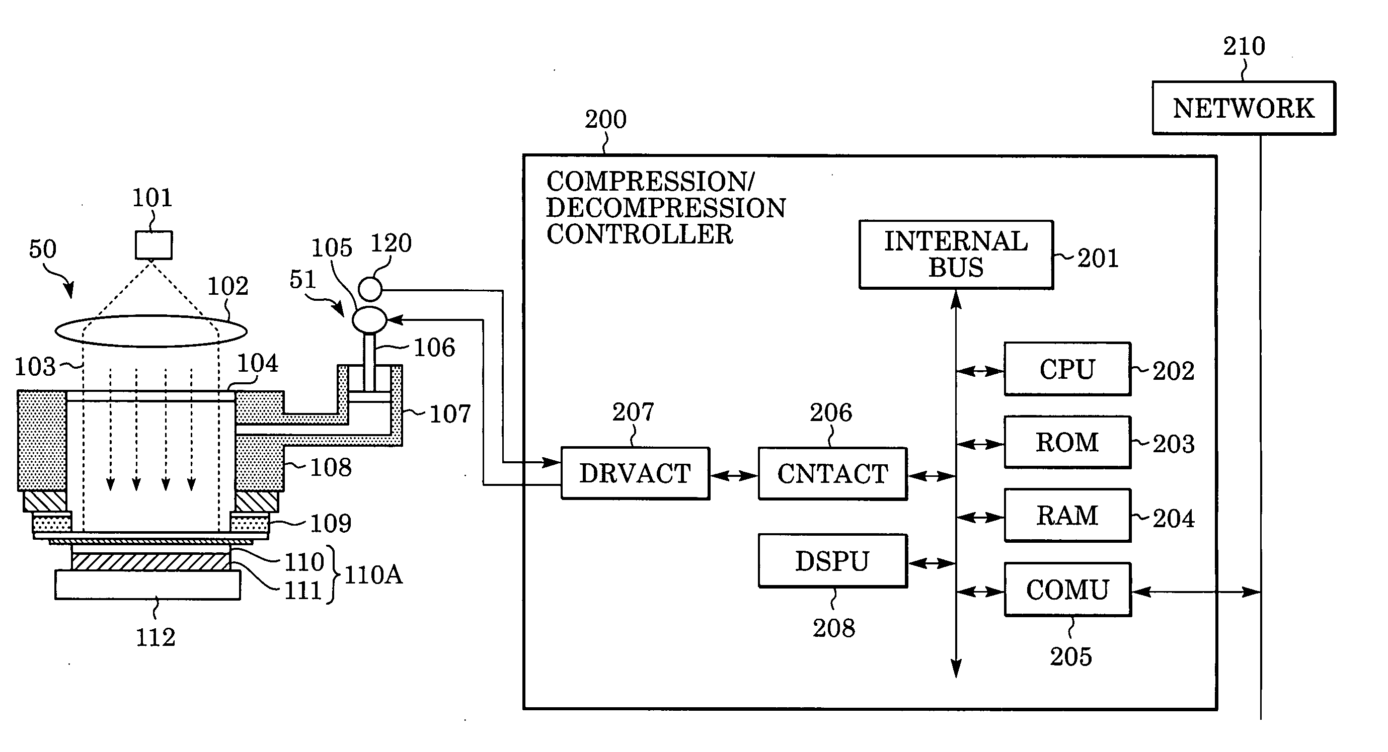
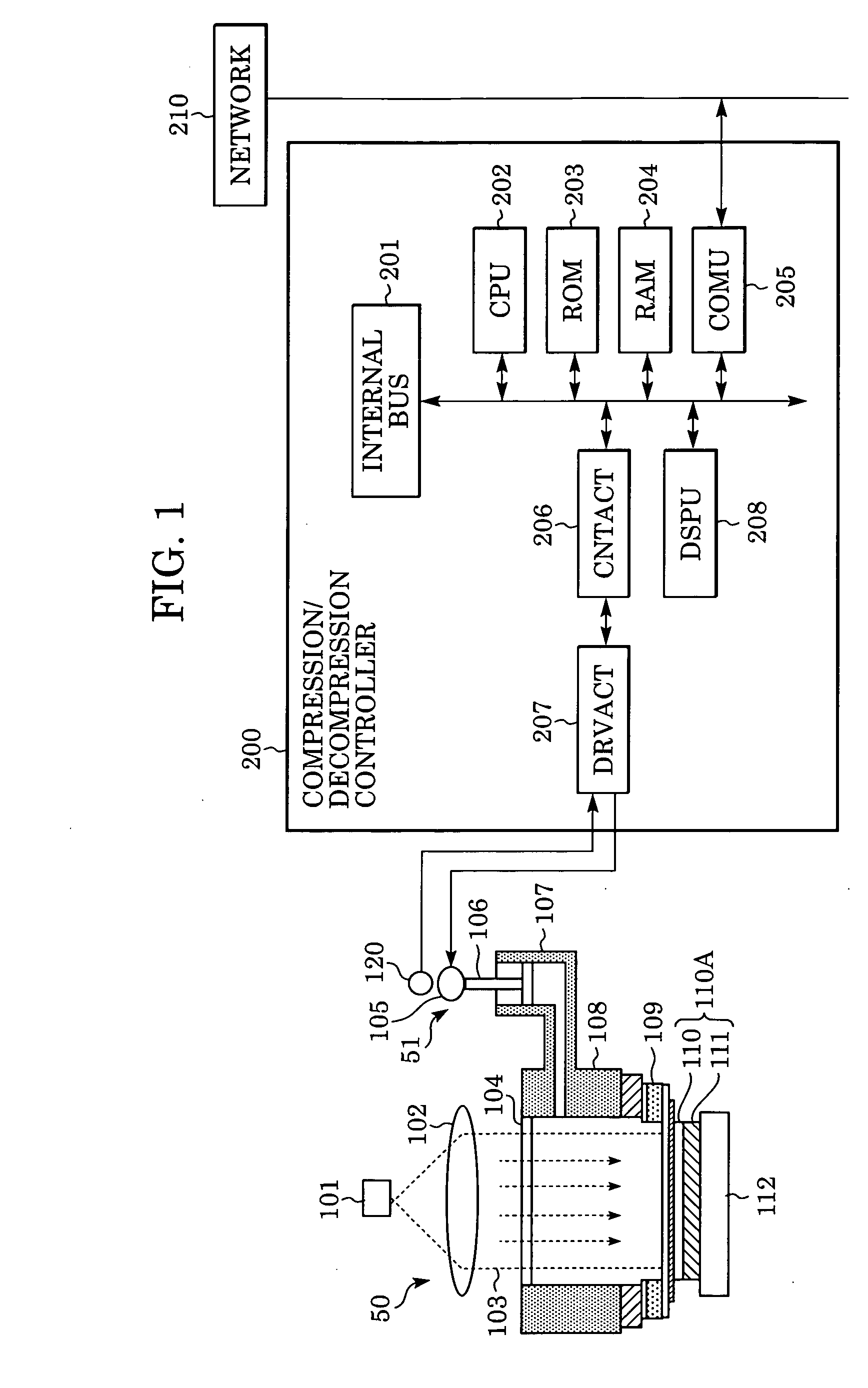
[0024]FIG. 1 is a schematic structural view of an exposure apparatus according to an embodiment of the present invention. Referring to FIG. 1, a nearfield exposure apparatus 50 includes a pressure regulating vessel 108, an exposure light source 101, a stage 112, and a compression / decompression actuator 51 for regulating the pressure in the pressure regulating vessel 108.

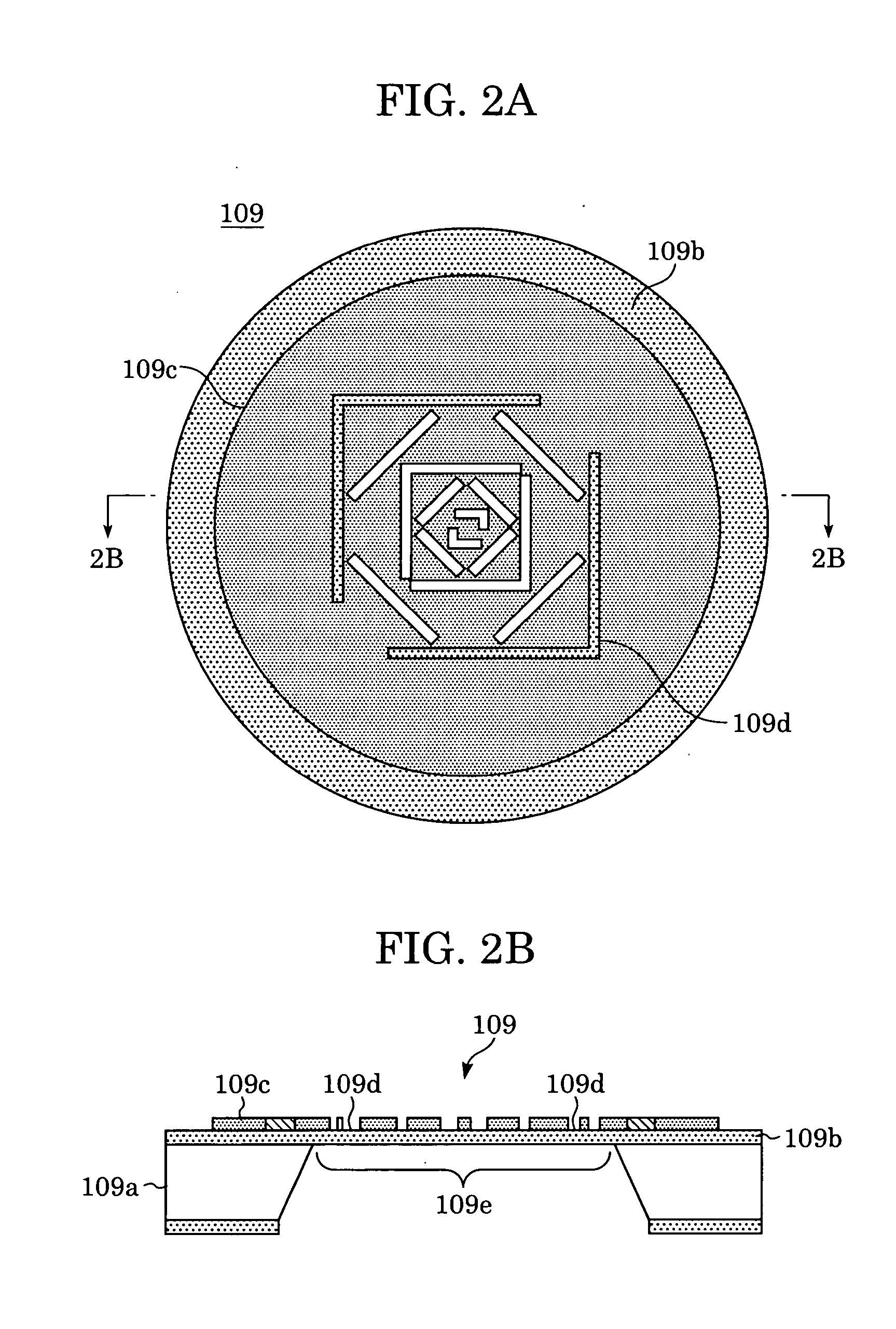
[0025] Also, in FIG. 1, an exposing mask 109 is attached on the bottom surface of the pressure regulating vessel 108. The exposing mask 109, as shown in FIGS. 2A and 2B, is composed of a mask support 109a, a mask base material 109b, and a light-exclusion film 109c. The light-exclusion film 109c is formed on the mask base material 109b, made of an elastic body for holding the thin film, so as to be retained thereon. The light-exclusion film 109c is provided with micro-openings 109d formed to have a desired pattern.

[0026] The exposing mask 109 is provided with an elastically deformable thin-film portion 109e formed i...


PUM


Abstract

An exposure apparatus for exposing an object to be exposed by elastically deforming an exposing mask having a micro-opening pattern so as to bring the exposing mask into contact with the object includes a compression / decompression section for elastically deforming the exposing mask with compression / decompression so as to bring the exposing mask into contact with the object or into detachment from the object; and a controlling section for controlling the compression / decompression operation with the compression / decompression section. The controlling section controls the compression / decompression operation with the compression / decompression section based on control data prepared in advance.

Description

BACKGROUND OF THE INVENTION [0001] 1. Field of the Invention [0002] The present invention relates to an exposure apparatus and an exposing method, and, in particular, relates to a light exposure performed in a state that an exposing mask having a micro-opening pattern is elastically deformed so as to come in contact with an object to be exposed. [0003] 2. Description of the Related Art [0004] Recently, along with progress and diversification in lithographic techniques used for manufacturing semiconductor devices and optical devices, various exposing methods have been proposed as emerging lithographic techniques. Among them, an exposing method is proposed in that micro-fabrication is enabled across the light diffraction limit using nearfield light. [0005] An exposure apparatus employing an exposing method using such nearfield light is proposed in that an exposing mask (membrane mask) made of an elastic body is elastically deformed so as to conform to a resist surface of the object fo...

Claims


Application Information

Patent Timeline
IPC IPC(8): G03B27/42
CPCG03F7/7035G03B27/42
Inventor KIRIYA, SHINOBU
Owner CANON KK
Learn More