Vehicular marker lamp

a technology of fluorescent lamps and fluorescent lamps, which is applied in the direction of fixed installation, lighting and heating apparatus, lighting support devices, etc., can solve the problems of high cost of lamps, inability to effectively use all light radiated from led lamps, etc., and achieve the effect of improving light distribution characteristics and brightness, increasing light-emitting area, and reducing the number of parts

Inactive Publication Date: 2006-02-16
KOITO MFG CO LTD
View PDF2 Cites 27 Cited by
  • Summary
  • Abstract
  • Description
  • Claims
  • Application Information

AI Technical Summary

Benefits of technology

[0008] The present invention was devised in light of the foregoing issues derived from the related art, and it is an object of the present invention to provide

Problems solved by technology

It is thus impossible to effectively use all light radiated from the LED as light radiated to

Method used


Image

  • Vehicular marker lamp
  • Vehicular marker lamp
  • Vehicular marker lamp

Examples


Embodiment Construction

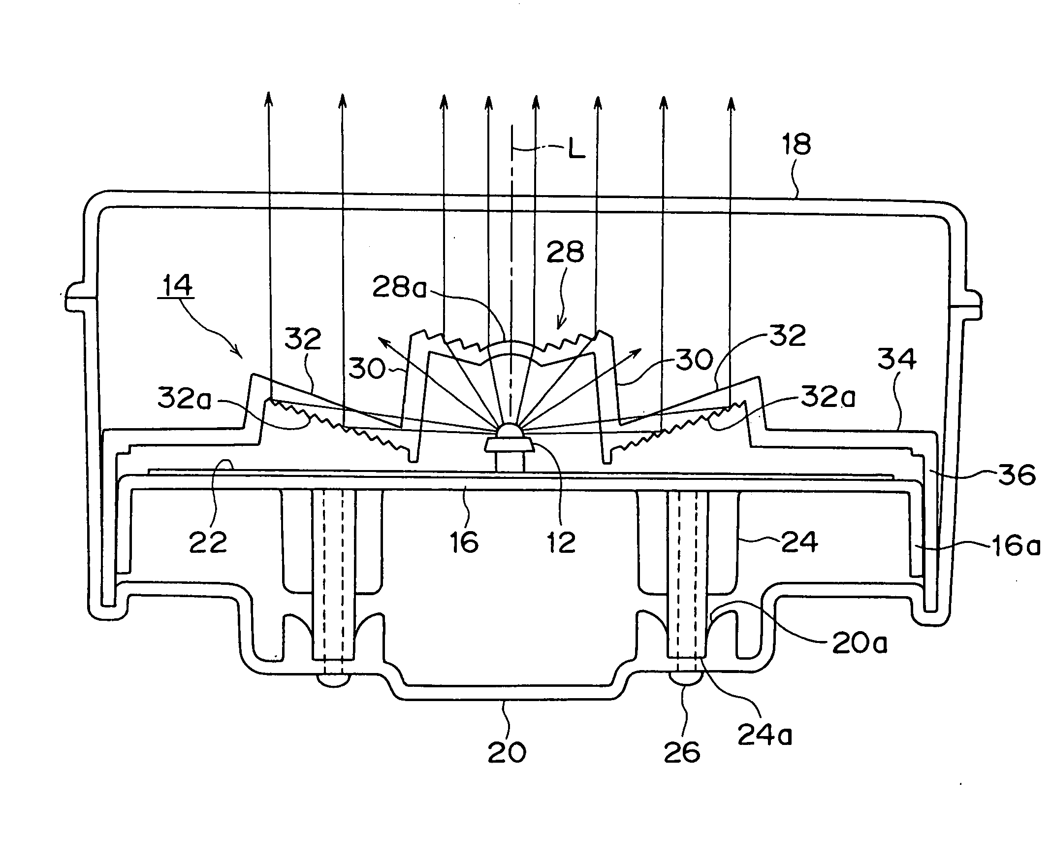
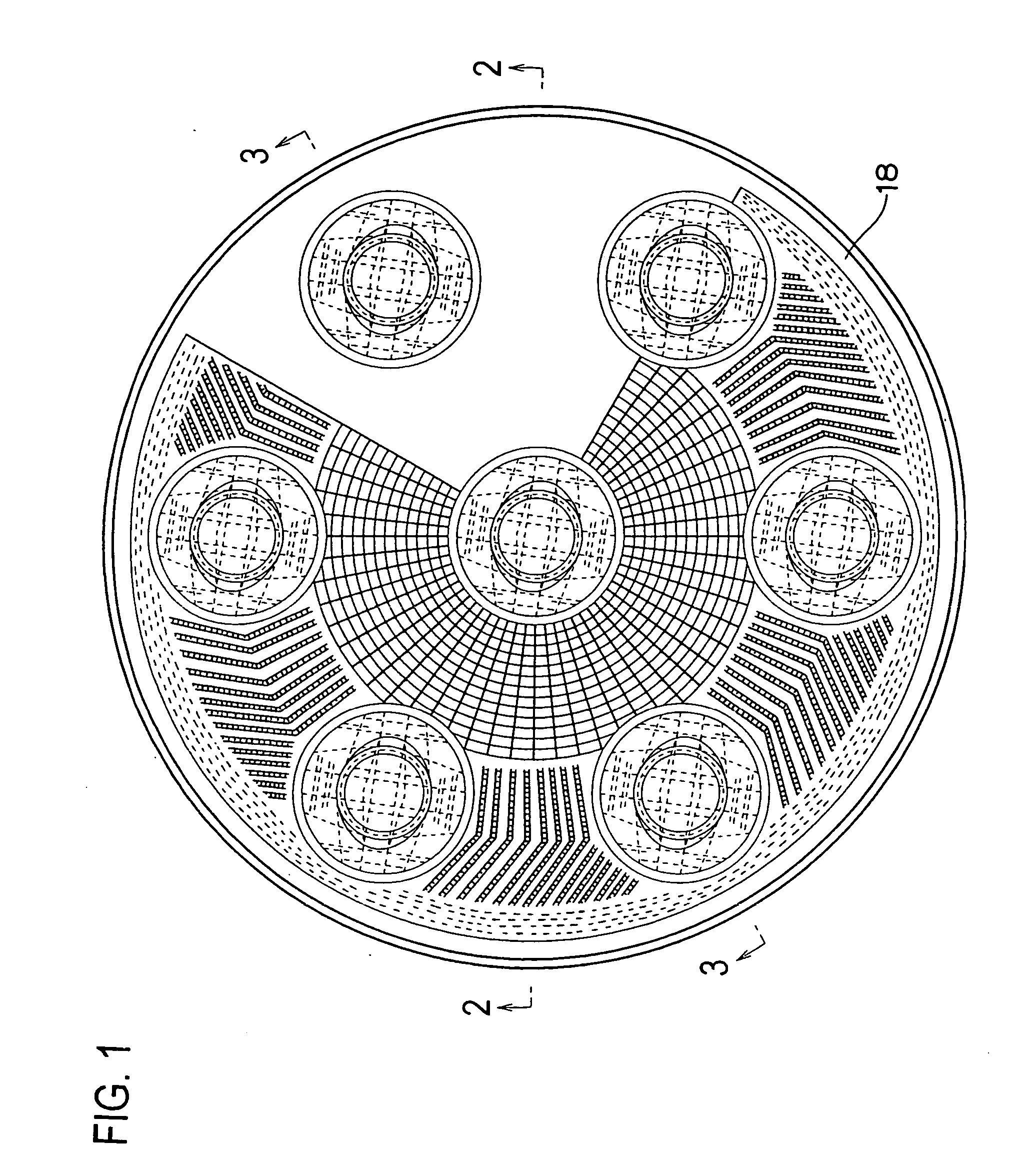
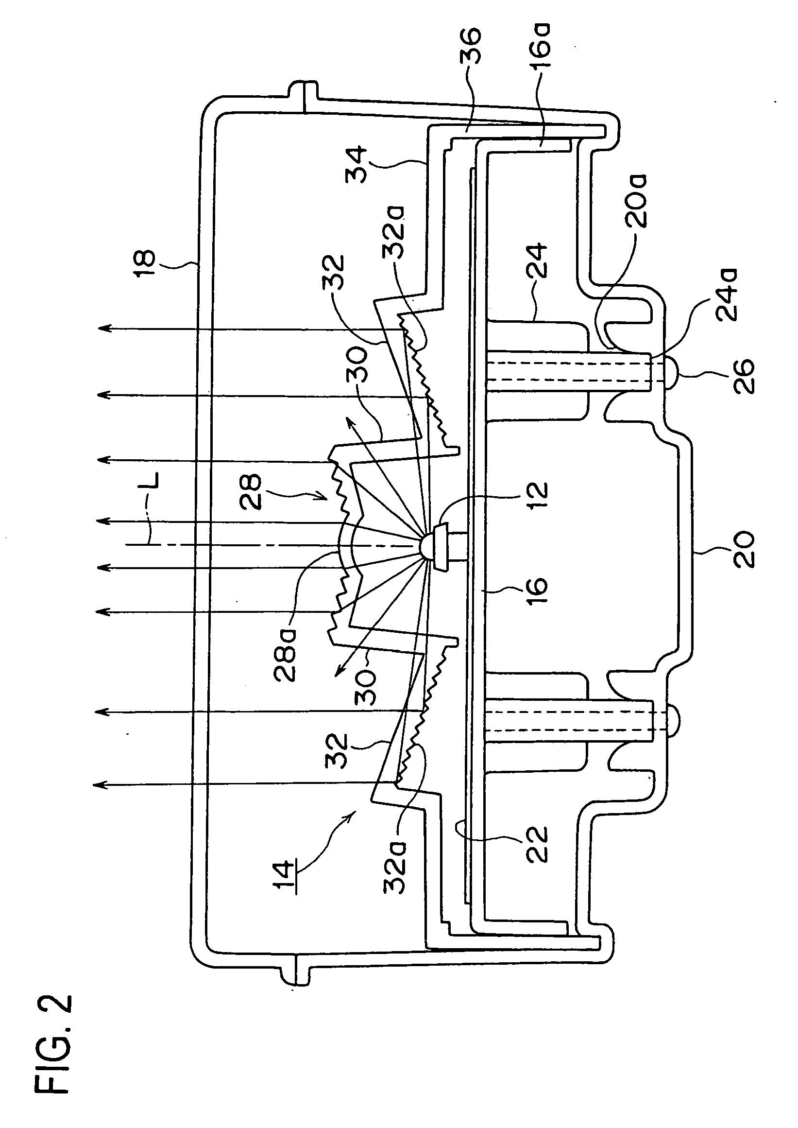
[0025] The vehicular marker lamp 10 shown in FIGS. 1 through 3 is a tail and stop lamp that is installed within a lamp mounted in the rear left comer or rear right comer of a vehicle. The lamp 10 comprises seven LEDs (light-emitting diodes) 12 that make the light source, an optical member 14 that corresponds to each LED 12, and a base member 16. The LEDs 12, along with the optical member 14, the base member 16 and the like, are accommodated within a lamp chamber that is defined by a front cover 18 formed in substantially a disc shape and a lamp body 20 formed in substantially a cylindrical shape.

[0026] The base member 16 provided corresponding to each LED 12 is a substantially disc-shaped integrated die cast element made of resin. Formed on the top surface side of the base member 16 is a bus bar 22 made of metal for connecting the terminal of each LED 12 to the light source, drive circuit (not shown) or the like; and a plurality of bosses 24 are further formed so as to protrude on ...


PUM


Abstract

A vehicular marker lamp including an LED, which is disposed with the optical axis in the forward direction of the lamp; and an optical member 14, whch is disposed in front of the LED for guiding light from the LED toward the front of the lamp. The optical member is formed with a lens portion, a connecting portion, and a reflective portion whch are integrated as a plate-shaped single element of a transparent resin. Light from the LED and directed to the front along the LED's optical axis is refracted by the lens portion and passes therethrough to the front of the lamp, and light deviating from the LED's optical axis passes through the connecting portion and is reflected by the reflective portion toward the front of the lamp.

Description

BACKGROUND OF THE INVENTION [0001] 1. Field of the Invention [0002] The present invention relates to a vehicular marker lamp and more particularly to a vehicular marker lamp which is used as a tail lamp, a stop lamp or the like and which employs LEDs as the light source. [0003] 2. Description of the Related Art [0004] A vehicular marker lamp that uses an LED (light-emitting diode) as its light source is already known. So as to increase the light-emitting area, this type of vehicular marker lamp uses a plurality of LEDs such that the light radiated from each LED is respectively radiated to the front lens. In the structure in which the light from the LED is simply radiated toward the front lens, if the LED is disposed such that the optical axis is in the direction of the front lens, light on the optical axis and in the surrounding vicinity is radiated toward the front lens, and light deviating from the optical axis is diffused; as a result, only a part of the diffused light is inciden...

Claims


Application Information

Patent Timeline
IPC IPC(8): F21S8/10
CPCF21S48/215F21S48/2212F21V7/0091F21V5/045F21S48/236F21S43/14F21S43/26F21S43/315
Inventor ASADA, KOHSEIKANEKO, SUSUMU
Owner KOITO MFG CO LTD
Why Eureka
Try Eureka