
Linear pump with vibration isolation

a linear, vibration isolation technology, applied in the field of pumps, can solve the problems of increasing bulk, adding hardware and cost, and rapid movement of single pistons, and achieve the effect of improving the isolation of the pump body

Inactive Publication Date: 2006-02-16
THOMAS IND INC
View PDF6 Cites 16 Cited by
  • Summary
  • Abstract
  • Description
  • Claims
  • Application Information

AI Technical Summary

Benefits of technology

[0011] This invention is a linear pump with improved isolation of the body of the pump form the internal working components.
[0015] The present invention thus provides a linear pump with less transfer of vibration from the internal working components to the pump enclosure. Better isolation of the internal vibrations provides for quieter operation, thereby increasing its desirability and allowing the pump to be used for a wider range of applications.

Problems solved by technology

Discreet operation of the pump can be obtained by insulating the housing, however, this adds bulk and can cause cooling problems.
Mufflers can be added at the output, however, this adds hardware and cost.
The rapid movement of the single piston generates considerable vibration.
However, when multiple springs are used, it can be difficult to achieve the prescribed spring rate to which the piston drive components of the pump have been tuned.
To ensure that the pump operates efficiently, it is thus important to achieve the intended spring rate and thus ensure the consistent orientation of the suspension springs, which can make pump assembly difficult.
Another problem is that the intake and exhaust valves of the valve head must open and close rapidly for each stroke of the piston.
Another problem is that the rapid opening and closing of the intake valve can cause pressure fluctuations or pulsations in the air flow upstream from the valve head.
These air pulsations can generate a low-frequency, rumbling noise.
Another problem confronting the design of compact linear piston pumps is eliminating pulsations in the output air stream.
Changing the operational frequency of the pump causes inefficiencies that can ultimately render the pump unusable for particular applications.
It can also exacerbate noise and vibration issues.
Yet another persistent problem in compact linear pump design is cooling.
As is well understood, heat adversely affects the pump efficiency and life.

Method used


Image

  • Linear pump with vibration isolation
  • Linear pump with vibration isolation
  • Linear pump with vibration isolation

Examples


Embodiment Construction

[0034] The present invention provides an axial or linear piston pump. The term pump used herein includes a device for providing either positive or negative pressure, and thus either acting as a vacuum pump or a compressor. The pump has a compact form factor, with a preferred operating range of 2-30 psi depending upon the application (however, the pump could be designed to operate at other pressures) with low external vibration and noise and less sensitivity to pump attachments (lines, hoses, tubing, etc.) downstream from the outlet.

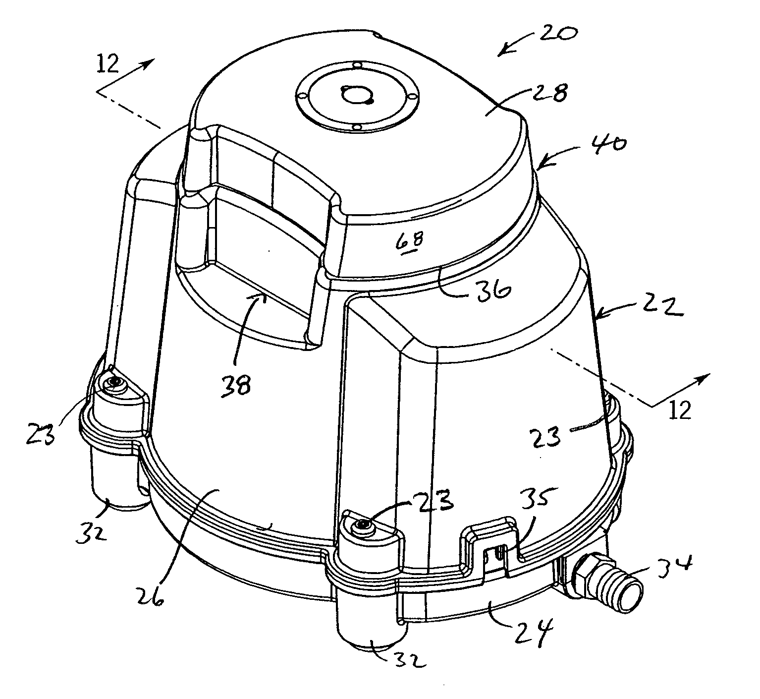
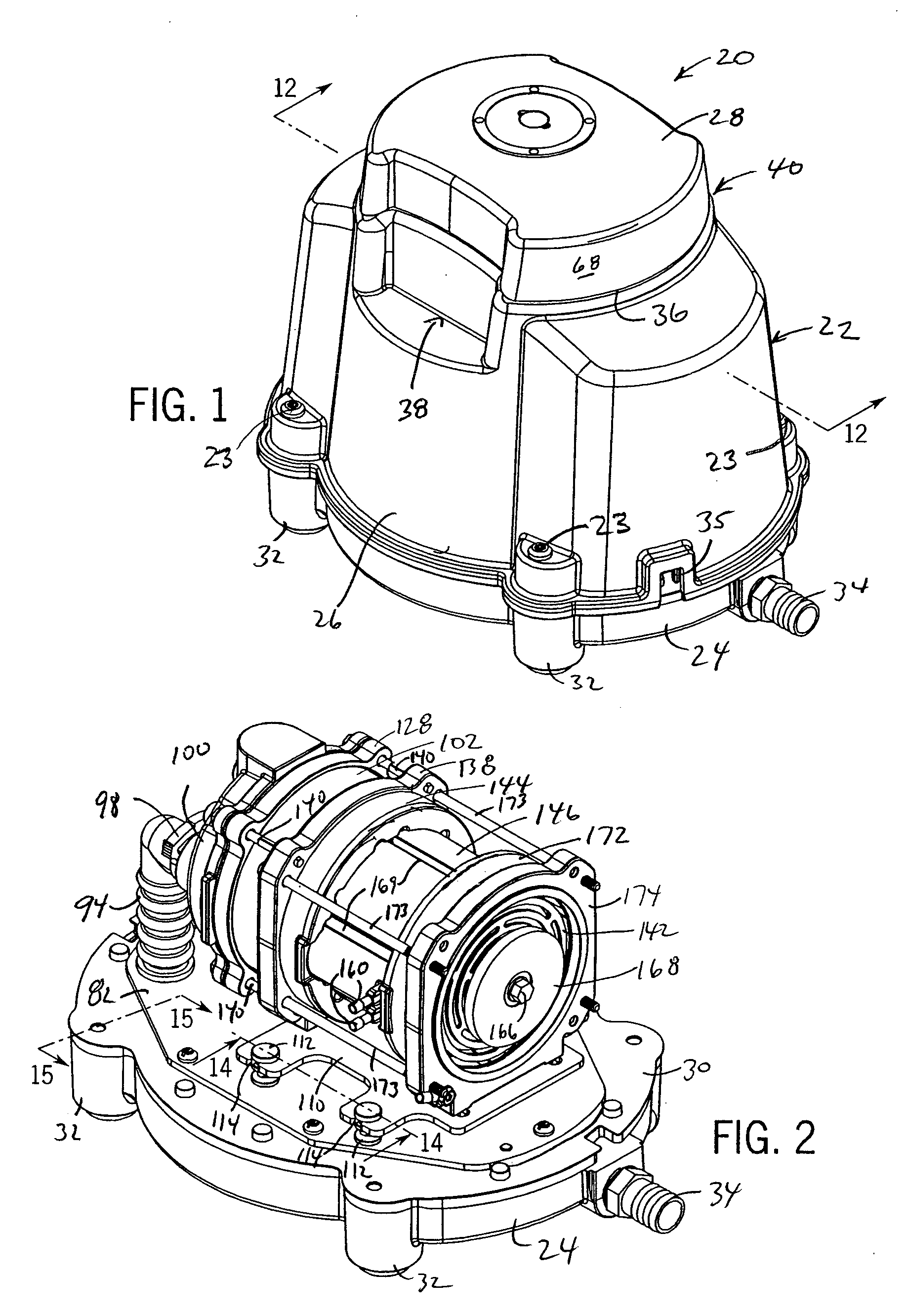
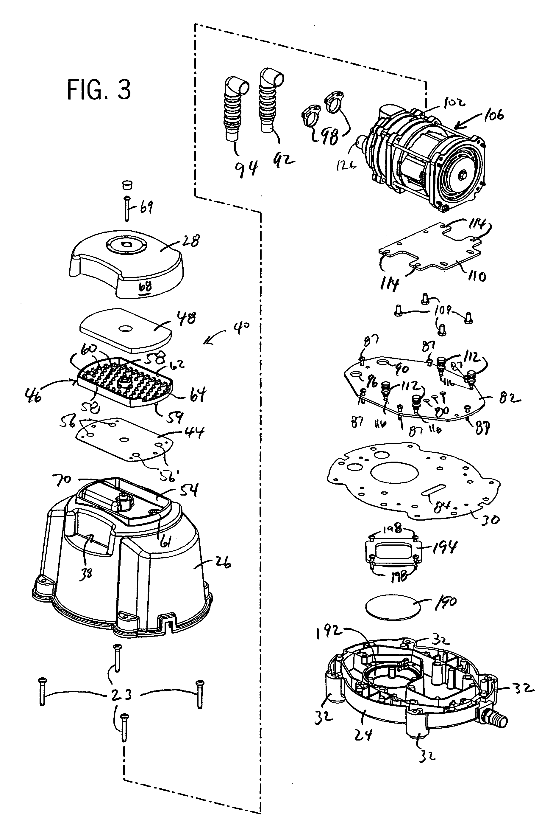
[0035] Referring to FIGS. 1-3, the pump, generally referred to in the drawings by reference number 20, has a compact housing 22 including a base 24, a shroud 26 and a top cover 28. The shroud 26 is bolted to the base 24 (via bolts 23), with a gasket 30 therebetween (see FIG. 15), and the cover 28 is bolted (via bolt 69) to the shroud 26. The base has four feet 32 to support the pump 20 and provides an opening for connecting a fitting 34 (see FIG. 11). Th...


PUM


Abstract

A linear pump having an axially aligned cylinder and piston arrangement driven by an electromagnet motor. The cylinder, piston and motor are contained in and coupled to a housing by a vibration isolation system. The vibration isolation systems has resilient mounts connected between a motor mount and a base of the housing as well as resilient tubing extending between a valve head of the cylinder and intake and exhaust chambers of the pump.

Description

CROSS-REFERENCE TO RELATED APPLICATIONS [0001] Not applicable. STATEMENT OF FEDERALLY SPONSORED RESEARCH OR DEVELOPMENT [0002] Not applicable. BACKGROUND OF THE INVENTION [0003] The present invention relates to pumps and in particular to compact linear piston pumps. [0004] Pumps for certain duties, such as oxygen concentration and sewage aeration, generally need to be compact and operate discreetly. It is thus important to properly muffle the working air as well as reduce vibration during operation of the pump without relying on a large, thick-walled housing to attenuate the sound and vibration. Discreet operation of the pump can be obtained by insulating the housing, however, this adds bulk and can cause cooling problems. Mufflers can be added at the output, however, this adds hardware and cost. [0005] Such compact linear pumps / compressors are often single cylinder devices with a small piston that reciprocates rapidly within a small cylinder to pressurize the air. The rapid movemen...

Claims


Application Information

Patent Timeline
IPC IPC(8): F04B35/04
CPCF04B39/0044F04B17/03
Inventor THOMAS, PAUL J.CHRISTIANSEN, ROSS P.
Owner THOMAS IND INC
Learn More