Automated testing framework for event-driven systems

a technology of event-driven systems and testing frameworks, applied in the field of computer programming, can solve the problems of insufficient system use for event-driven, listener-based systems, and high level of human involvement in the testing process

Inactive Publication Date: 2006-02-16
LINKEDIN
View PDF18 Cites 25 Cited by
  • Summary
  • Abstract
  • Description
  • Claims
  • Application Information

AI Technical Summary

Benefits of technology

[0013] The present invention provides techniques for automated testing in event-driven systems. One or more user-provided test system event listeners listen for generated events and updates test system status accordingly. A user-provided test suite definition implements a test framework interface, thereby defining the structure of a test suite. This test suite is executed, referring to the test system status to determine when to move to a next stage (e.g., to a next test case or next test module). Test system status may also be updated directly from a test case or test module (e.g., when the test designer determines that the tested code will not generate events that can be leveraged for test status information).

Problems solved by technology

Software testing for a complex application may require executing a large number of test cases to exercise sufficient coverage of paths through the software.
This level of human involvement in the testing process is very time-consuming and therefore costly.
In particular, automated testing for systems that are event-based can be difficult.
While automated test systems are known in the art, these systems are not sufficient for use with event-driven, listener-based systems. FIG. 1 illustrates problems that commonly arise, and will now be described.
Furthermore, additional problems may result due to the unpredictable completion time of event processing that is triggered by Method1.
The unpredictable duration of the event processing may therefore cause one or more of these methods to be invoked during the wrong system state, such that the entire outcome of Testcase_1 becomes invalid.
Furthermore, as time goes on, more functionality might be added to the systems under test, and each method might therefore take longer to run.
As a result, one might have to repeatedly adjust the time delay in all existing test cases.
In short, the intentional delay approach is error-prone and labor intensive, and is not a viable solution.

Method used


Image

  • Automated testing framework for event-driven systems
  • Automated testing framework for event-driven systems
  • Automated testing framework for event-driven systems

Examples


Embodiment Construction

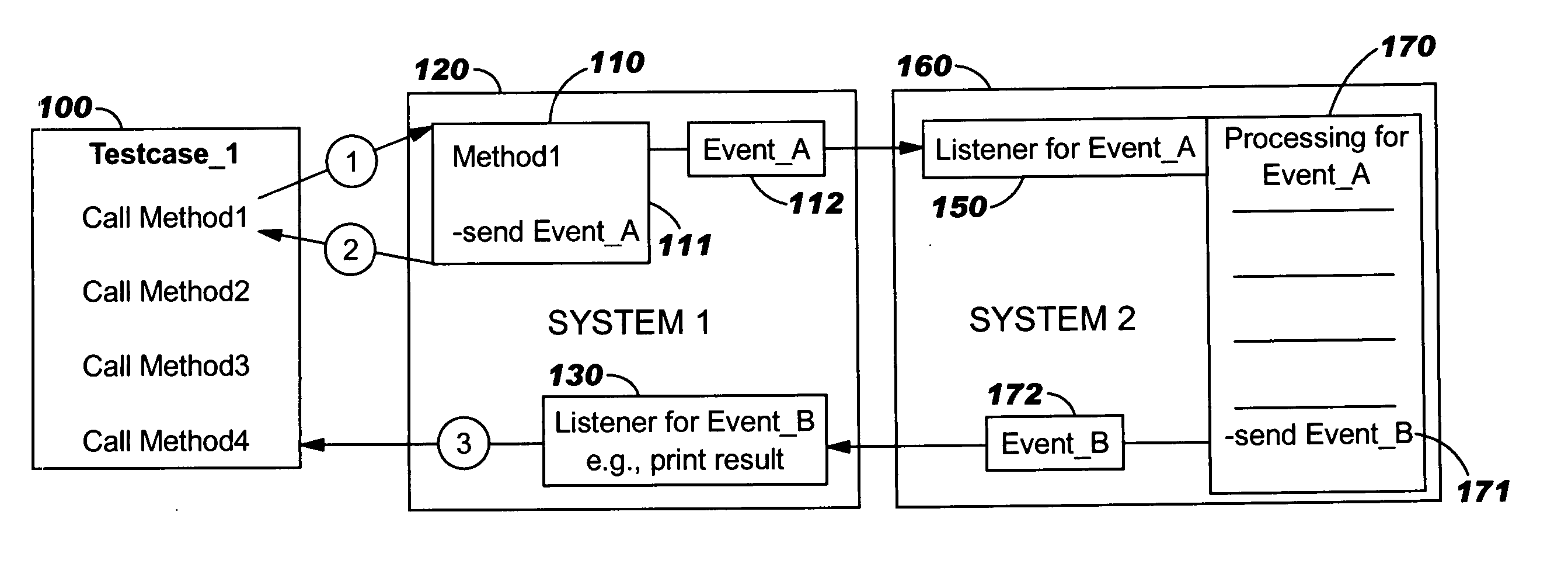
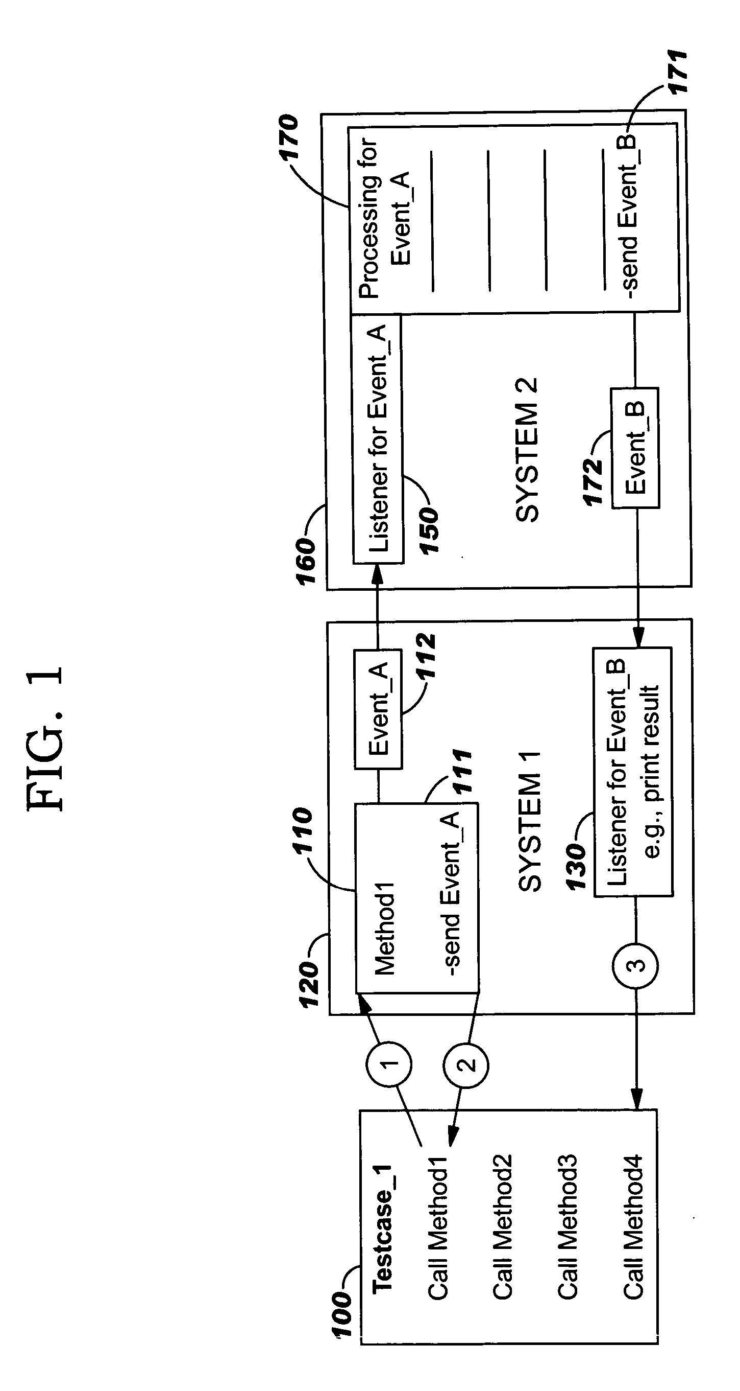
[0021] The present invention provides techniques for automated testing in event-driven systems. In an event-driven system, events are a primary means of communication among processes. Each type of event has a deterministic and logical response that the system will produce. For example, whenever Event_A from the sample test case in FIG. 1 happens, it is known that the system needs to process that event for an unknown period of time. And, whenever Event_B from the sample test case happens, it is known that the system has completed the processing of Event_A. This information can be used to determine when the system is still busy with the processing of code pertaining to Method1, and when it is not, according to preferred embodiments.

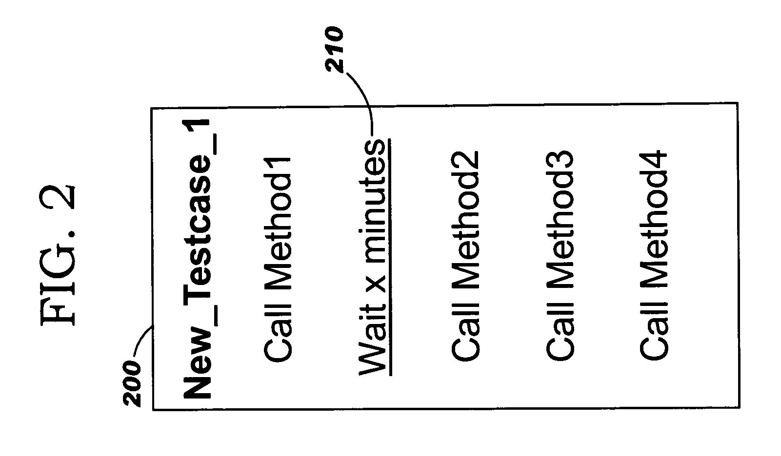
[0022] Preferred embodiments leverage this information, using events that communicate the start and end of activity. Thus, automated test execution according to the present invention uses listeners in event-driven systems to listen to events, and responsiv...


PUM


Abstract

Techniques for programmatically coordinating, and synchronizing execution of, automated testing in event-driven systems. One or more user-provided test system event listeners listen for generated events and updates test system status accordingly. A user-provided test suite definition invokes a test framework interface, thereby defining the structure of a test suite. This test suite is executed, referring to the test system status to determine when to move to a next stage (e.g., to a next test case or next test module). Test system status may also be updated directly from a test case or test module (e.g., when the test designer determines that the tested code will not generate events that can be leveraged for test status information).

Description

BACKGROUND OF THE INVENTION [0001] 1. Field of the Invention [0002] The present invention relates to computer programming, and deals more particularly with programmatically coordinating, and synchronizing execution of, automated testing in event-driven systems. [0003] 2. Description of the Related Art [0004] Software testing for a complex application may require executing a large number of test cases to exercise sufficient coverage of paths through the software. In years past, human test personnel were largely responsible for carrying out the testing process, and in particular, for selecting which test cases should be executed, in which order, and under what conditions. A software test engineer would therefore invoke a test case, determine whether it completed successfully, and based on that determination, decide whether another test case should be invoked—or perhaps whether the test case should be re-executed after some type of software modification. [0005] This level of human invo...

Claims


Application Information

Patent Timeline
Patent Type & Authority Applications(United States)
IPC IPC(8): G06F11/00
CPCG06F11/3672
Inventor FUNG, JANE C.O'FARRELL, WILLIAM G.
Owner LINKEDIN
Why Eureka
Try Eureka