Permanent magnet motor

a permanent magnet, motor technology, applied in the direction of magnetic circuit rotating parts, manufacturing stator/rotor bodies, magnetic circuit shape/form/construction, etc., can solve the problems of reducing the cogging torque, unable to eliminate the stator yoke, and unable to generate torque, etc., to achieve high accuracy, reduce the cogging torque, and low vibration

Inactive Publication Date: 2006-02-23
SHIN ETSU CHEM IND CO LTD
View PDF7 Cites 49 Cited by
  • Summary
  • Abstract
  • Description
  • Claims
  • Application Information

AI Technical Summary

Benefits of technology

[0014] It is an object of the present invention to reduce the cogging torque of servomotors, electric power steering motors, and others, and to provide a permanent magnet motor with which it is possible to realize a robot in which a servomotor that is capable of positioning with high accuracy is used and an electric power steering that generates low vibrations and provides good steering feel by eliminating a component of the cogging torque caused by permanent magnets.
[0026] As will be described in detail below, according to the present invention, it is possible to reduce the cogging torque caused by variations in the permanent magnets, and to realize a robot in which a servomotor that is capable of positioning with high accuracy is used and an electric power steering motor that generates low vibrations and provides good steering feel.

Problems solved by technology

This is caused by the hysteresis loss of the stator yoke.
However, even with such a method, the duodenary, twenty-fourth order, and thirty-sixth order components, which are attributed to the permanent magnets, cannot be eliminated.
However, in the case of the permanent magnet motor in which a reduced cogging torque is achieved by using any of the combinations of the number of poles and the number of salient poles shown in Table 1, the difference between the number of poles and the number of salient poles is small, so that when skewing is performed, different magnetic poles come to be opposed to one salient pole at the same time, and thus driving torque is not generated.
Accordingly, there has been no effective measure for reducing such cogging torque caused by permanent magnets, and there has been a problem in that there are practical limitations to industrial processes for reducing the cogging torque by suppressing variations in the permanent magnets.

Method used


Image

  • Permanent magnet motor
  • Permanent magnet motor
  • Permanent magnet motor

Examples


working example 1

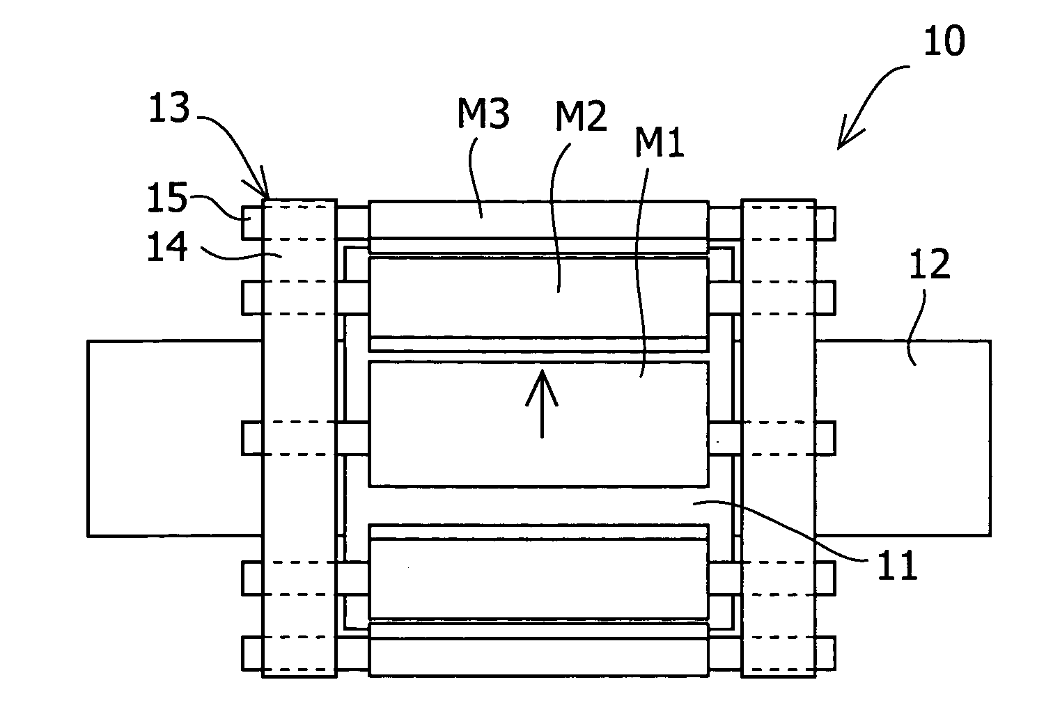
[0079] A permanent magnet motor according to Working Example 1 had the same configuration as the permanent magnet motor according to Comparative Example 2 described above, except for items particularly described below, such as the position of the permanent magnets and the magnet holding member (see FIG. 11). It should be noted that a shaft runs through the center of the rotor yoke made of a low carbon steel, the shaft being made of the same material. In Working Example 1, the permanent magnets were held by the magnet holding member after a permanent magnet was moved in the circumferential direction, as shown in FIG. 1. Here, as the magnet holding member, magnet holding yokes having tap holes and hexagon socket set screws serving as the magnet holders were used. Moreover, the stator yoke was made by the rotational laminating method.

[0080] First, the amount of change in the cogging torque was measured when the permanent magnet was moved in the circumferential direction. More specific...

working example 2

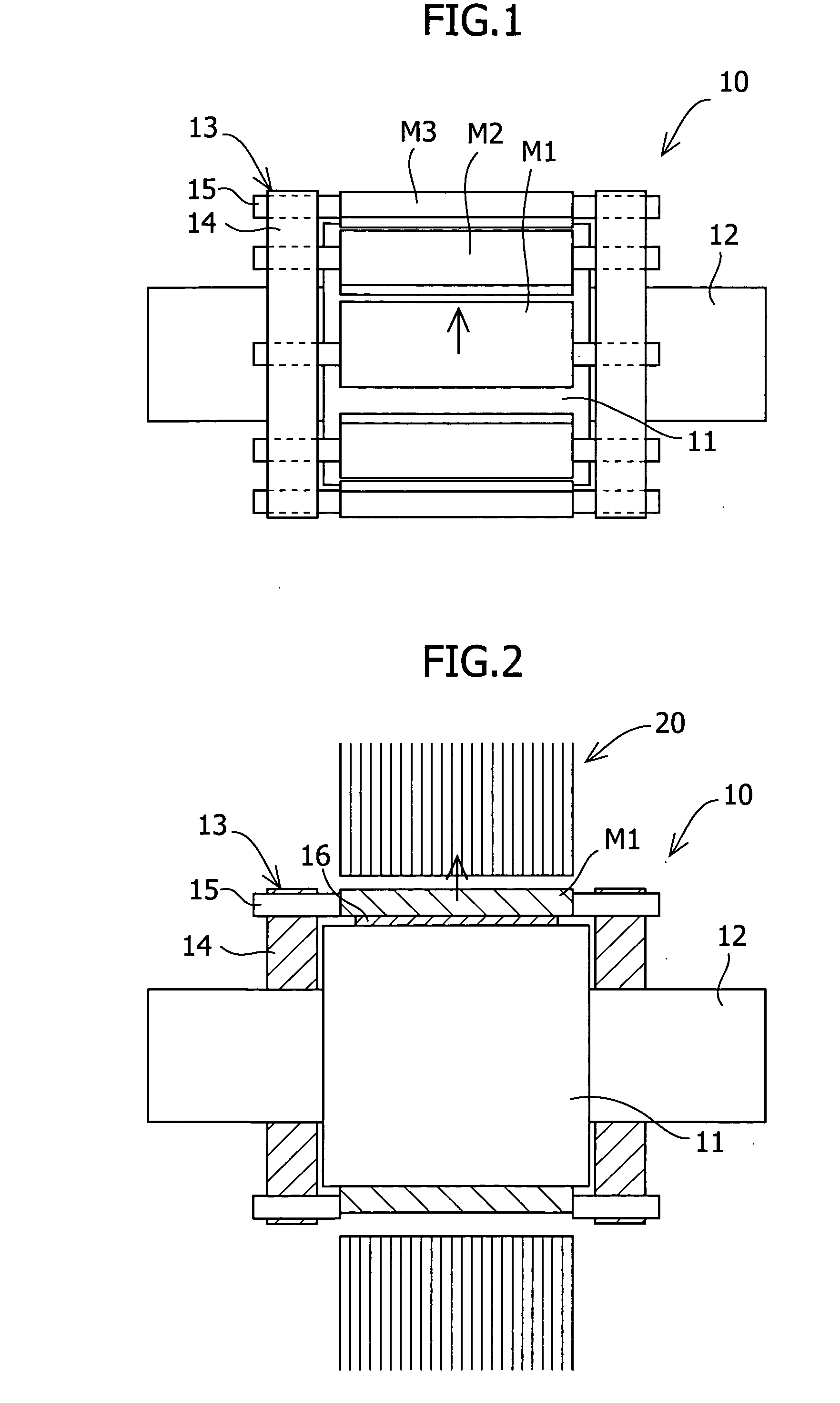
[0086] Working Example 2 was the same as Working Example 1 except that the permanent magnet was moved in the radial direction as shown in FIG. 2. First, the amount of change in the cogging torque when the permanent magnet was moved in the radial direction was measured. Non-magnetic SUS was used for the non-magnetic shim. More specifically, the amount of change in the cogging torque that occurred when the magnet M1 in FIG. 11 was moved in the radial direction was measured, and as in the above-described comparative example, the components of the cogging torque that changed were analyzed using Fourier analysis. FIG. 9 shows the results of the Fourier analysis in which the waveform of the amount of change in the cogging torque when the permanent magnet was moved in the radial direction was divided into components of respective orders of the waveform. As in the case where the permanent magnet was moved in the circumferential direction, the components of the cogging torque that changed we...

working example 3

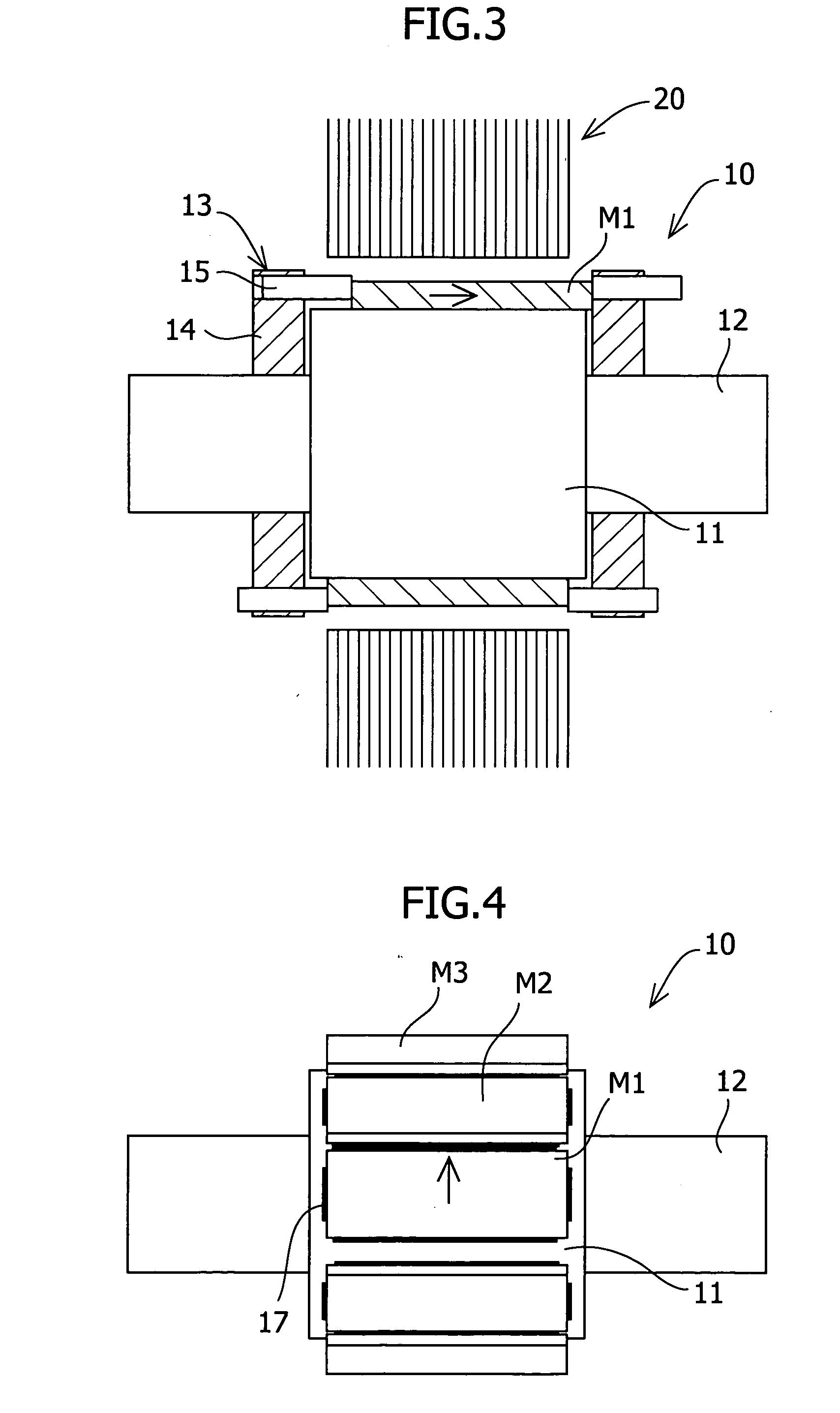
[0088] Working Example 3 was the same as Working Example 1 except that the permanent magnet was moved in the axial direction as shown in FIG. 3. First, the amount of change in the cogging torque when the permanent magnet was moved in the axial direction was measured. More specifically, the amount of change in the cogging torque that occurred when the magnet M1 shown in FIG. 11 was moved in the axial direction was measured, and the components of the cogging torque that changed were analyzed using Fourier analysis. FIG. 10 shows the results of the Fourier analysis in which the waveform of the amount of change in the cogging torque when the permanent magnet was moved in the axial direction was divided into components of respective orders of the waveform. As in the cases where the permanent magnet was moved in the circumferential direction or in the radial direction, almost all of the components of the cogging torque were of duodenary order. Moreover, the amount of change in the cogging...


PUM

PropertyMeasurementUnit
residual magnetic flux densityaaaaaaaaaa
lengthaaaaaaaaaa
lengthaaaaaaaaaa

Abstract

To reduce the cogging torque of servomotors, electric power steering motors, and others, there is provided a permanent magnet motor comprising: a rotor 10 comprising a rotor yoke 11 and a plurality of permanent magnets (M1-M10); and a stator 20 comprising a stator yoke 22, salient magnetic poles 21, and armature windings 23, wherein at least one of the permanent magnets is disposed in an adjustment position that is displaced from a corresponding reference position in at least one of the circumferential, radial, and axial directions of the rotor yoke, and the plurality of permanent magnets excluding the permanent magnet disposed in the adjustment position is disposed in the reference positions, and wherein the adjustment position is set so that the permanent magnet motor in which at least one of the plurality of permanent magnets is disposed in the adjustment position has a smaller cogging torque than a permanent magnet motor in which all of the plurality of permanent magnets are disposed in the reference positions; and a method for adjusting a cogging torque of a permanent magnet motor.

Description

RELATED APPLICATION [0001] This application claims priority from Japanese Patent Application No. 2004-240222, filed Aug. 20, 2004, the disclosure of which is incorporated by reference herein in its entirety. BACKGROUND OF THE INVENTION [0002] 1. Field of the Invention [0003] The present invention relates to permanent magnet motors, and specifically to permanent magnet motors for servomotors and electric power steering motors etc., with reduced cogging torque. [0004] 2. Description of Related Art [0005] There has been a demand for miniaturized and low-loss servomotors and electric power steering motors, and by employing a motor in which armature windings are concentratedly wound around respective salient magnetic poles of a stator, the amount of the windings that extend beyond an end portion of the stator is reduced, and thus the length of the motor and copper loss in the windings are reduced. Also, there has been a strong demand for reducing the cogging torque of motors in order to ...

Claims


Application Information

Patent Timeline
Patent Type & Authority Applications(United States)
IPC IPC(8): H02K5/24H02K1/27H02K15/02H02K15/03H02K21/16
CPCH02K1/278H02K29/03Y10T29/49009Y10T29/49012Y10T29/49004
Inventor MIYATA, KOJI
Owner SHIN ETSU CHEM IND CO LTD
Why Eureka
Try Eureka