Packet transmission in a wireless communication system using multiple antennas

a wireless communication system and packet transmission technology, applied in wireless communication, data switching networks, wireless communication, etc., can solve problems such as radio resource waste, packet re-transmission using two or four transmitting antennas may have problems,

Inactive Publication Date: 2006-02-23
LG ELECTRONICS INC
View PDF6 Cites 42 Cited by
  • Summary
  • Abstract
  • Description
  • Claims
  • Application Information

AI Technical Summary

Benefits of technology

[0027] Accordingly, the present invention is directed to packet transmission in a wireless communication system that substantially obviates one or more problems due to limitations and disadvantages of the related art.

Problems solved by technology

However, the conventional packet re-transmission using two or four transmitting antennas may have problems, such as waste of radio resources.

Method used


Image

  • Packet transmission in a wireless communication system using multiple antennas
  • Packet transmission in a wireless communication system using multiple antennas
  • Packet transmission in a wireless communication system using multiple antennas

Examples


first embodiment

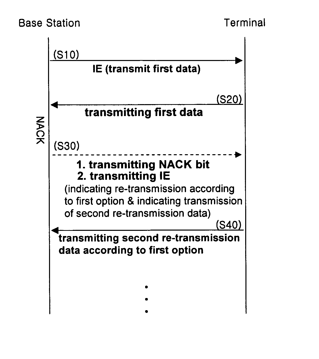
[0082]FIG. 9 shows a data re-transmission procedure in accordance with the present invention. As shown, the base station informs the terminal about the data to be transmitted via the Information Element (IE) in order to receive a signal of the terminal (step S10). Then, the terminal transmits corresponding data to the base station (step S20) and the base station receives such data and determines whether the received data is an ACK or a NACK.

[0083] If the received signal is a NACK, that is, if the received data has an error, the base station transmits a NACK signal and an IE to the terminal (step S30). In such case, the base station may inform the terminal, by means of the IE, about the NACK signal by using a single bit and about which re-transmission vector is to be used. Then, the terminal performs re-transmission accordingly (step S40).

[0084] The second and third embodiments of the present invention show situations of a downlink HARQ data transmission.

second embodiment

[0085]FIG. 10 shows a data re-transmission procedure in accordance with the present invention. The base station transmits first data and an IE to the terminal (step S110). Here, the IE has a default value representing a particular re-transmission option.

[0086] After the initial (first) data arrives at the terminal, if the data has an error, the terminal selects one of the re-transmission options and transmits to the base station, a NACK signal according to the selected option (step S120).

[0087] Upon receiving the NACK signal from the terminal, the base station includes the received NACK option information into the IE in order to inform the terminal about which option the NACK signal (received by the base station) belongs to, and transmits the IE (containing the received NACK option information) when sending the subsequent (second) re-transmission data. Here, the NACK option information is used to provide re-confirmation to the terminal regarding the signal that the terminal had tra...

third embodiment

[0088]FIG. 11 shows a data re-transmission procedure in accordance with the present invention. The base station selects a NACK option (number) that is to be transmitted by a terminal, and then, transmits such to the terminal (step S210). That is, the base station determines a NACK signal of a certain option to be transmitted by the terminal if the data contains an error, and adds the determined option information to the IE. The base station then transmits the IE to the terminal together with the data.

[0089] When the data from base station arrives and if such data is detected to contain an error, the terminal transmits to the base station, the NACK signal of the option that had been designated the base station (step S220). Thereafter, when different data is transmitted, the base station includes the previously determined option information in the IE and transmits it to the terminal (step S230).

[0090] The following Tables show exemplary formats of the Information Element (IE) that ma...


PUM


Abstract

A method of retransmitting packet data in a wireless communication system comprises receiving a link map information element from a transmitting station having three antennas to achieve space time transmit diversity, wherein first, second and third packet data are transmitted from first, second and third antenna of the transmitting station, respectively. The method also comprises transmitting a non-acknowledgement signal to the transmitting station if at least one packet data from the transmitting station is not properly decoded. The method also comprises receiving the packet data from the transmitting station, wherein at least two of retransmitted packet data are transmitted from different antennas of the transmitting station, and one of retransmitted packet data is transmitted from the same antenna of the transmitting station. The retransmitted packet data are received with an information element comprising a retransmission count associated with a number of retransmission made by the transmitting station.

Description

CROSS-REFERENCE TO RELATED APPLICATIONS [0001] Pursuant to 35 U.S.C. § 119(a), this application claims the benefit of earlier filing date and right of priority to Korean Application No. 2004-0064551, filed on Aug. 17, 2004, and Korean Application No. 2005-0019788, filed on Mar. 9, 2005, the contents of which are hereby incorporated by reference herein in their entirety. FIELD OF THE INVENTION [0002] The present invention relates generally to a wireless communication system and, more particularly, to packet transmission in a wireless communication system. BACKGROUND OF THE INVENTION [0003] Multimedia services in wireless communication systems are in increasing demand. Developments are being made to achieve data transmissions with higher capacity and higher speed. Therefore, efficient use of limited radio frequency resources is of increasing importance. To this end, a multiple-input multiple-output (MIMO) system using a multi-antenna has been employed. The multi-antenna system uses tw...

Claims


Application Information

Patent Timeline
Patent Type & Authority Applications(United States)
IPC IPC(8): H04L12/28H04B7/005
CPCH04B7/0604H04L1/0625H04W28/04H04L1/1887H04L1/1812
Inventor IHM, BIN-CHULCHUN, JIN-YOUNGJIN, YONG-SUK
Owner LG ELECTRONICS INC
Why Eureka
Try Eureka