Finishing machine

a finishing machine and burr technology, applied in the field of finishing machines, can solve the problems of overcutting parts of workpieces, the inability to remove burrs by one cutting action, etc., and achieve the effect of effectively finishing work

Active Publication Date: 2006-02-23
FANUC LTD
View PDF9 Cites 19 Cited by
  • Summary
  • Abstract
  • Description
  • Claims
  • Application Information

AI Technical Summary

Benefits of technology

[0014] In the present invention, machining is conducted in such a manner that the position of the burr is found and the burr is removed from the position. Therefore, the finishing work can be effectively conducted.

Problems solved by technology

In the case where the size of the burr is relatively large, this burr cannot be removed by one cutting action for burr removing.
Accordingly, there is a possibility that overcut portions of the workpiece may be generated.

Method used


Image

  • Finishing machine
  • Finishing machine
  • Finishing machine

Examples


Embodiment Construction

[0021] Referring to the drawings, an embodiment of the present invention will be explained below.

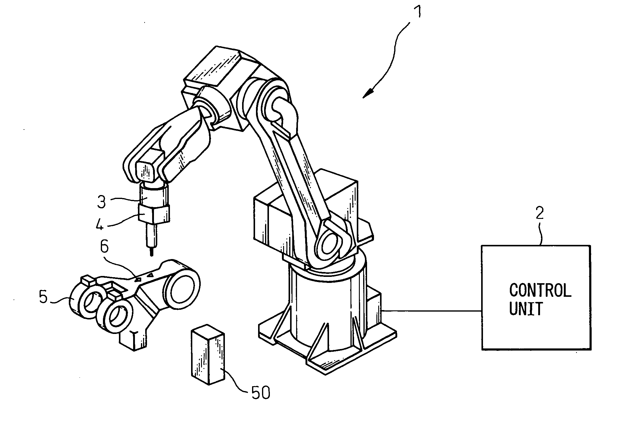
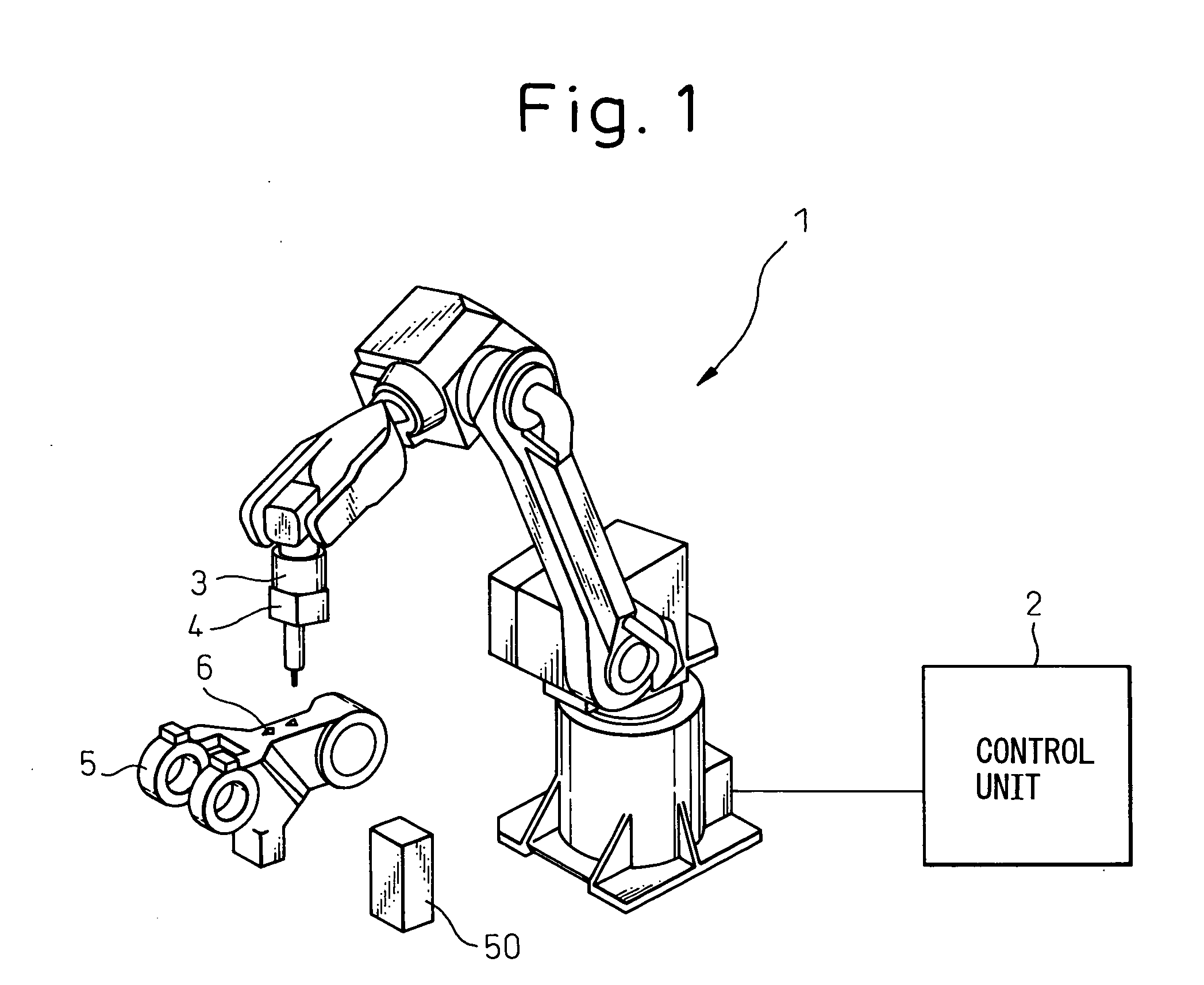
[0022]FIG. 1 is a view showing an outline of an embodiment of the present invention. In this embodiment, the workpiece 5, such as a mechanical part, is fixed at a predetermined position on a working table (not shown), and the machining tool 4 is attached to a forward end portion of the arm of the robot body 1 via the force sensor 3. The finishing machine of the present invention removes the burr 6 of the workpiece 5 using this machining tool 4. In this connection, in FIG. 1, reference numeral 2 indicates a robot control unit. The robot body 1 is controlled and driven by this control unit 2. The machining tool 4 is of the type in which the cutting blade is rotated. This machining tool 4 is also controlled and driven by this control unit 2.

[0023] The force sensor 3 measures a pushing force of the machining tool 4 when machining is being conducted or the surface shape of the workpiece 5 i...


PUM

PropertyMeasurementUnit
shapeaaaaaaaaaa
forceaaaaaaaaaa
force measurementaaaaaaaaaa

Abstract

A surface of a workpiece, from which the burr is removed, is traced when a machining tool is pressed onto the surface of the workpiece under force control so as to find the positional data of the surface shape (S1). This positional data is corrected by an error caused by a bend of a robot (S2). The thus obtained positional data is compared with the target shape of the surface, from which the burr is removed, obtained from CAD data (S6, S10). A shift of the surface shape in the normal line direction is found (S7, S11). The burr generation start position, the burr generation end position and the height of the burr are found by the shift start position (S8), the shift end position and the shift size (S14). A machining program is made which is composed of a pass connecting the burr end position with the burr start position and also composed of a cutting pass for removing the burr, and the thus made machining program is executed (S16, S17). As the burr position is found and the burr is removed when the machining tool is moved to the burr position, the burr can be effectively removed. Due to the foregoing, it is possible to provide a finishing machine characterized in that useless burr removing actions can be reduced and, further, that the overcutting of a workpiece can be prevented.

Description

BACKGROUND OF THE INVENTION [0001] 1. Field of the Invention [0002] The present invention relates to a finishing machine for removing a burr, from a surface of a workpiece such as a mechanical part, by a robot. [0003] 2. Description of the Related Art [0004] Concerning methods of removing a burr from a workpiece such as a mechanical part, a method of automatically removing the burr by a robot is known. According to the method, under the condition that the workpiece is fixed at a predetermined position, a machining tool for removing the burr is attached to the robot. Next, by means of pressure control, in which a mechanical floating mechanism operated by a spring or pneumatic pressure is used, or by means of pressure control in which software is used, while the machining tool is being pushed onto a surface of a workpiece, on which the burr is formed, at a predetermined force, the surface of the workpiece, on which the burr is formed, is moved so that the burr can be removed. The foll...

Claims


Application Information

Patent Timeline
Patent Type & Authority Applications(United States)
IPC IPC(8): B23C1/16
CPCG05B19/4163Y10T409/301792Y10T409/304256Y10T409/303472Y10T409/30084Y02P90/02
Inventor BAN, KAZUNORISATO, TAKASHIHATANAKA, KOKORO
Owner FANUC LTD
Why Eureka
Try Eureka