Test device and method for colored particle immunoassay

Inactive Publication Date: 2006-02-23
CHARLTON DAVID E +1
View PDF0 Cites 39 Cited by
  • Summary
  • Abstract
  • Description
  • Claims
  • Application Information

AI Technical Summary

Benefits of technology

[0017] The use of the colored particle detection system in combination with the filtration means, the concentrating effect of flow of the sample, and the ease of comparison between the color

Problems solved by technology

False positives can also be troublesome, particularly with agglutination and other rapid detection methods such as dipstic

Method used


Image

  • Test device and method for colored particle immunoassay

Examples


Embodiment Construction

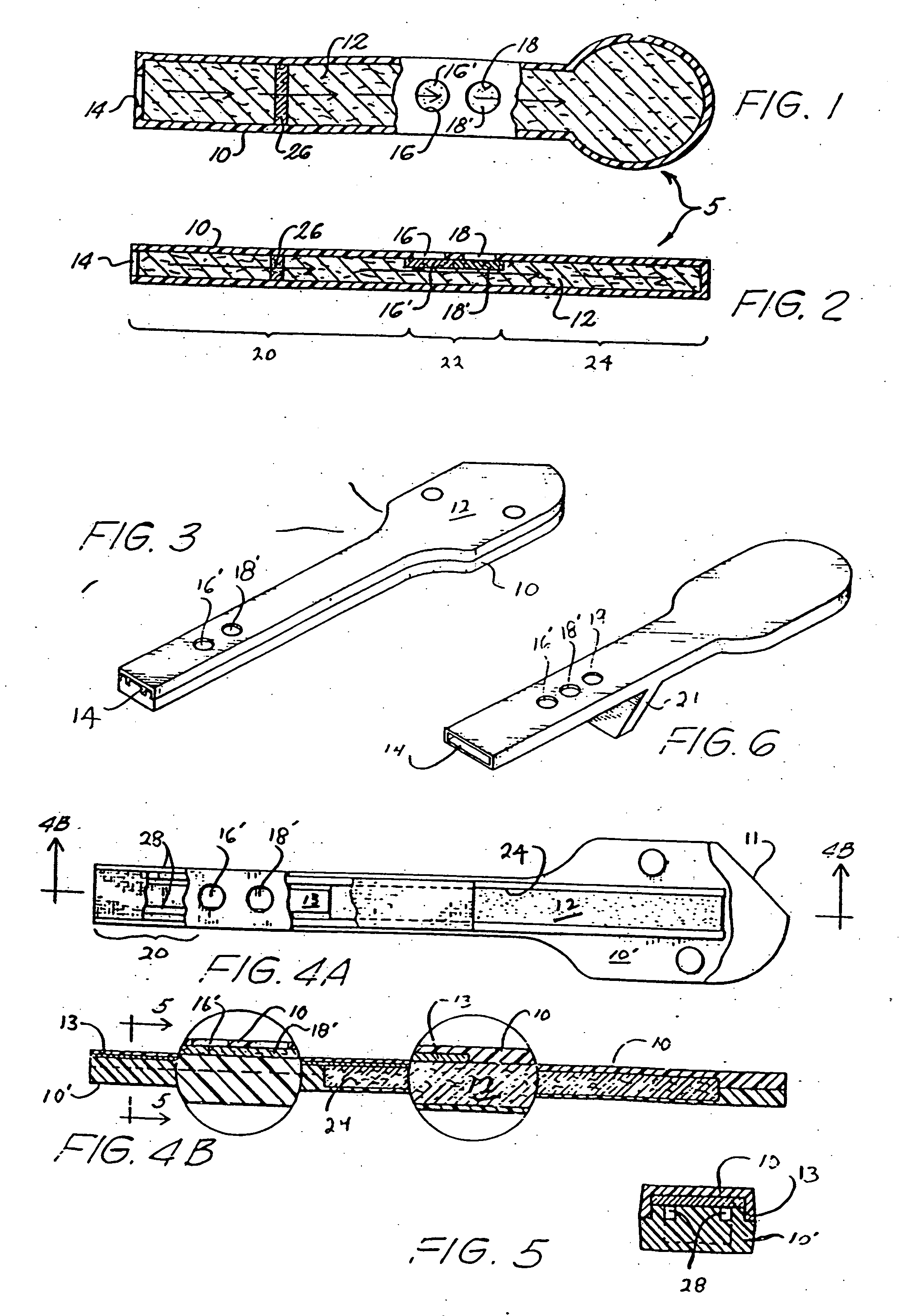
[0044] The currently preferred test device embodying the invention is shown in FIGS. 3, 4A, 4B, and 5. A modification of the device depicted in FIG. 3 is shown in FIG. 6, and includes a second control site 19 in addition to control site 16′ and test site 18′, as well as a stand 21 useful for maintaining the test cell in an incline position with the reservoir downhill. When a test sample is applied to inlet 14, gravity as well as sorption aids in transporting the sample along the flow path.

[0045] As shown in FIGS. 3, 4A, 4B, and 5, the preferred test cell of the invention differs from the exemplary device discussed above and shown in FIGS. 1 and 2 in certain of its more specific internal features. Specifically, the casing comprises a pair of interfitting polymeric parts including a U-shaped top part 10 which, when the device is assembled, interfits with lower part 10′. Top and bottom parts 10 and 10′ may be connected through a hinge region 11. The bottom section 10′ defines a pair o...


PUM


Abstract

Disclosed is a test cell and a method for detection of a preselected ligand in a liquid sample such as a body fluid. The test cell includes an elongate outer casing which houses an interior permeable material capable of transporting an aqueous solution and defining a sample inlet, a test volume, and a reservoir volume. The reservoir volume is disposed in a section of the test cell spaced apart from the inlet and is filled with sorbent material. The reservoir acts to receive liquid transported along a flow path defined by the permeable material and extending from the inlet and through the test volume. In the test volume is a test site which includes a first protein having a binding site specific to a first epitope of the ligand immobilized in fluid communication with the flow path. The test site can be observed through a window of the casing.

Description

BACKGROUND OF THE INVENTION [0001] This invention relates to assays for ligands, e.g., antigens, in a liquid sample such as a body fluid. More particularly, the invention relates to a method and apparatus for the detection of a ligand in a body fluid such as urine using a conjugate comprising colored particles and a novel flow-through test cell. [0002] Many types of ligand-receptor assays have been used to detect the presence of various substances, often generally called ligands, in body fluids such as urine. These assays involve antigen antibody reactions, synthetic conjugates comprising radioactive, enzymatic, fluorescent, or visually observable metal sol tags, and specially designed reactor chambers. In all these assays, there is a receptor, e.g., an antibody, which is specific for the selected ligand or antigen, and a means for detecting the presence, and often the amount, of the ligand-receptor reaction product. Most current tests are designed to make a quantitative determinati...

Claims


Application Information

Patent Timeline
IPC IPC(8): G01N33/566B01L3/00G01N33/53G01N33/543G01N33/74G01N33/76G01N37/00
CPCB01L3/5023Y10T436/255B01L2300/0825B01L2400/0406G01N33/54313G01N33/54366G01N33/743G01N33/76Y10S435/81Y10S435/97Y10S436/817Y10S435/805Y10S436/81Y10S436/818Y10S436/814B01L2300/0681
Inventor CHARLTON, DAVID E.MILLER, NEAL W.
Owner CHARLTON DAVID E
Why Eureka
Try Eureka