Transmission power amplifier unit

a technology of transmission power amplifier and amplifier, which is applied in the direction of amplifier modification, power management, wireless communication, etc., can solve the problems of a comparatively long time required to settle in the steady state, the call processing cannot keep pace, and the inability to receive, so as to improve the output power (transmission power) of the transmission power amplifier unit, the non-linear distortion of the main amp can be compensated quickly, and the gain increase.

Inactive Publication Date: 2006-02-23
SAITO YUTAKA +1
View PDF12 Cites 30 Cited by
  • Summary
  • Abstract
  • Description
  • Claims
  • Application Information

AI Technical Summary

Benefits of technology

[0023] Accordingly, an object of the present invention increase the transmission power of a high-power amplifier linearly with time when a station is established.
[0024] Another object of the present invention is to so arrange it that when power is introduced to a high-power amplifier (i.e., when the amplifier is started up), an excessive current will not enter a sub-amp and cause destruction of the sub-amp, and to so arrange it that non-linear distortion of a main amp can be compensated for quickly.
[0025] A transmission power amplifier unit of a base-station apparatus for compensating for non-linear distortion of a transmission power amplifier by feed-forward control is provided with (1) a gain varying unit for varying gain of the transmission power amplifier unit, and (2) a controller for controlling the gain varying unit. At start-up of (introduction of power to) the transmission power amplifier unit, the controller determines whether the base-station apparatus is in a blossoming mode or breathing mode, maximizes gain of the transmission power amplifier unit if the mode is the blossoming mode and increases the gain of the transmission power amplifier unit gradually if the mode is the breathing mode.
[0027] If the above arrangement is adopted, the transmission power amplifier unit holds the gain constant at establishment of a station because the base station will be in the blossoming mode. When a station is established, therefore, output power (transmission power) of the transmission power amplifier unit can be increased linearly with time. Further, when power is introduced to a transmission power amplifier unit replaced for the sake of testing or maintenance, the base station is in the breathing mode and, hence, the transmission power amplifier unit gradually raises gain. As a result, it can be so arranged that a sub-amp will not be destroyed owing to input of excessive power. Moreover, non-linear distortion of a main amp can compensated for quickly.

Problems solved by technology

In other words, if a large amount of power is suddenly output to enlarge a cell when a station is established, calls from a large number of terminals concentrate at one time, call processing cannot keep pace and a variety of problems arise.
Otherwise reception will not be possible even if transmission is or transmission will not be possible even if reception is.
Further, in feed-forward control, a comparatively long period of time is required to settle in the steady state if a large signal is suddenly applied.
If the transmission power SOUT of the base station ceases varying linearly with respect to time, then it is no longer possible to exercise the original control that attempts to enlarge the cell (the transmit area) gradually in proportion to time.
A particular problem is that since the base station that establishes the link is changed over owing to the reception power of the mobile terminal, the base station that establishes the link will be changed over frequently unless transmission power control of the base station is performed smoothly when a station is set up.
A further problem is that a difference develops between the transmittable area and receivable area so that, depending upon the region, transmission is possible but reception is not, or vice versa.

Method used


Image

  • Transmission power amplifier unit
  • Transmission power amplifier unit
  • Transmission power amplifier unit

Examples


first embodiment

(B) First Embodiment

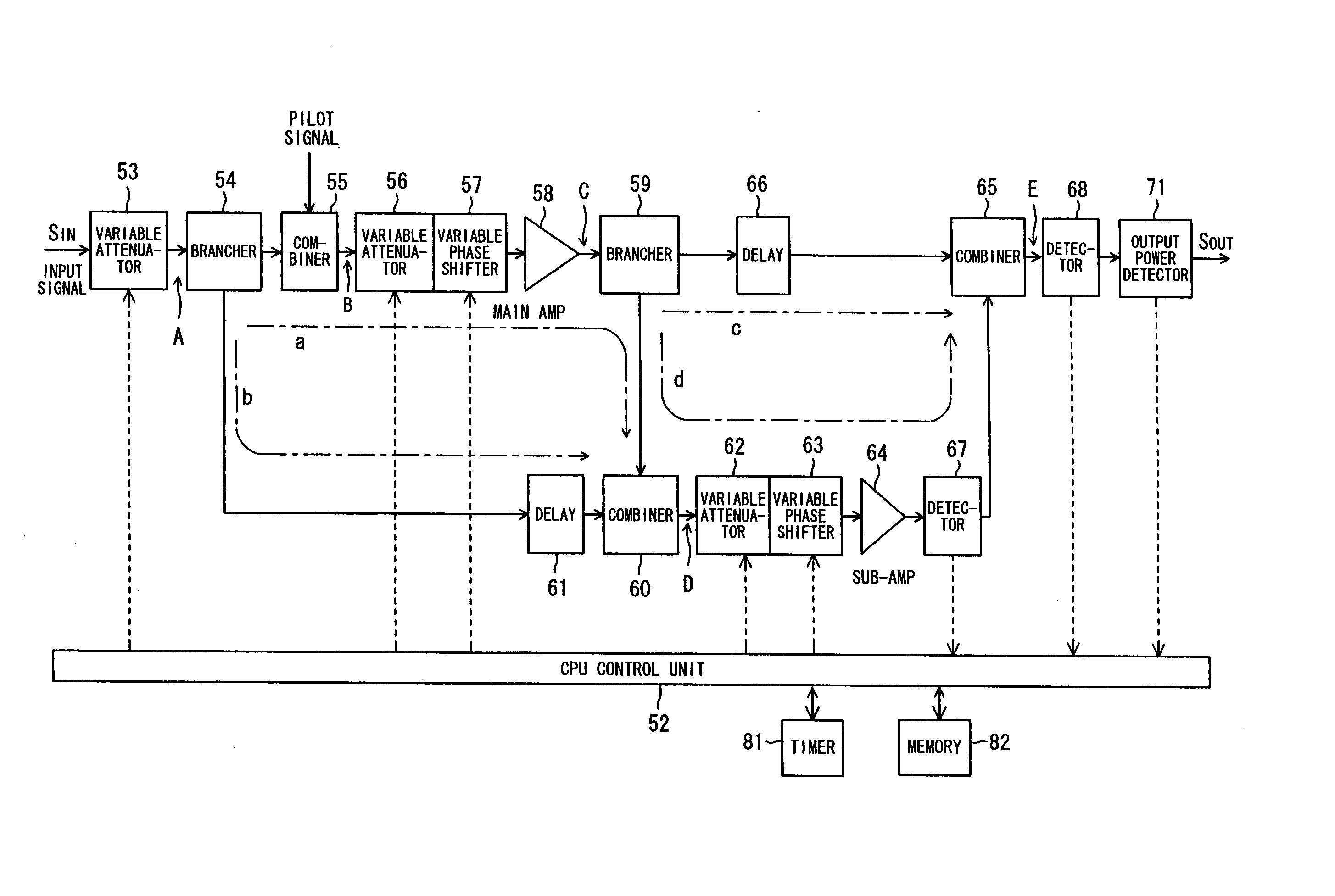
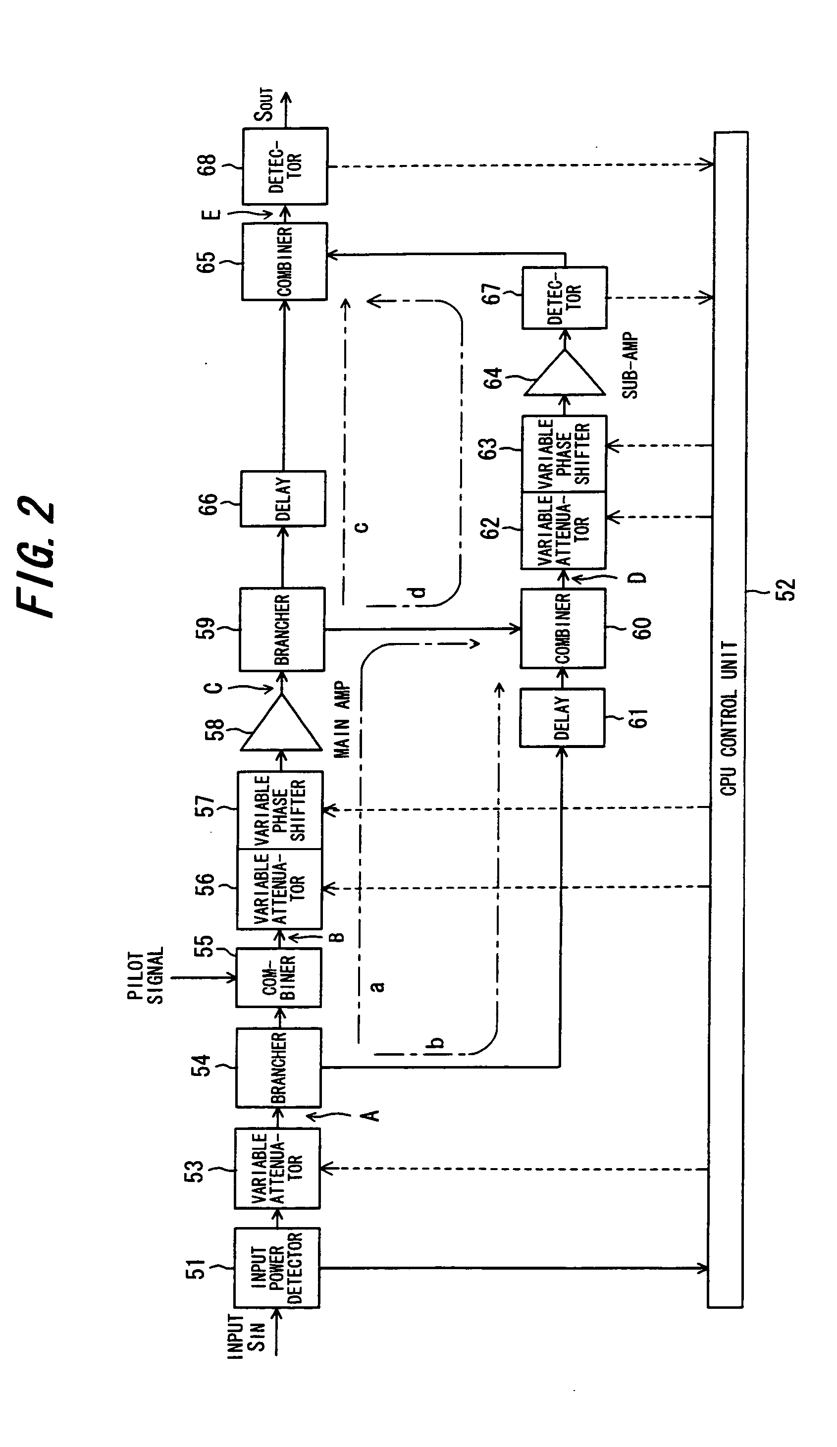
[0050]FIG. 2 is a diagram showing the structure of a high-power amplifier (HPA) according to a first embodiment of the present invention.

[0051] An input power detector 51, which is provided on the input side of the high-power amplifier, detects the input power SIN and inputs the result to a control unit 52. FIG. 3 is a diagram showing the structure of the level detector 51. The input power SIN is branched by a coupler 51a such as a unidirectional coupler, and one branched signal is input to a variable attenuator 53. The other branched signal is input to an RSSI (Receive Signal Strength Indicator) circuit 51c via an isolator 51b. The RSSI circuit 51c converts the power of the input signal to voltage and inputs the voltage to an amplifier 51d, where the signal is subjected to the necessary amplification and then input to an AD converter 51e. The AD converter 51e converts the input voltage to a digital signal and inputs the digital signal to the control unit 52.

[0...

second embodiment

(C) Second Embodiment

[0070]FIG. 6 is a diagram showing the structure of a high-power amplifier (HPA) according to a second embodiment of the present invention. Components identical with those of the first embodiment of FIG. 2 are designated by like reference characters. This embodiment differs-from the first embodiment in that: [0071] (1) an output power detector 71 is provided instead of the input power detector 51; [0072] (2) the control unit 52 converts the detected value from the output power detector 71 to input power based upon the gain of the high-power amplifier; and [0073] (3) mode discrimination and attenuation control (gain control) are carried out in accordance with the flowchart of FIG. 4 based upon the input power obtained by the conversion.

[0074] As shown in FIG. 7, the output power detector 71 has a structure identical with that of the input power detector 51 of the first embodiment. The output power SOUT is branched by a coupler 71a such as a unidirectional coupler...

third embodiment

(D) Third Embodiment

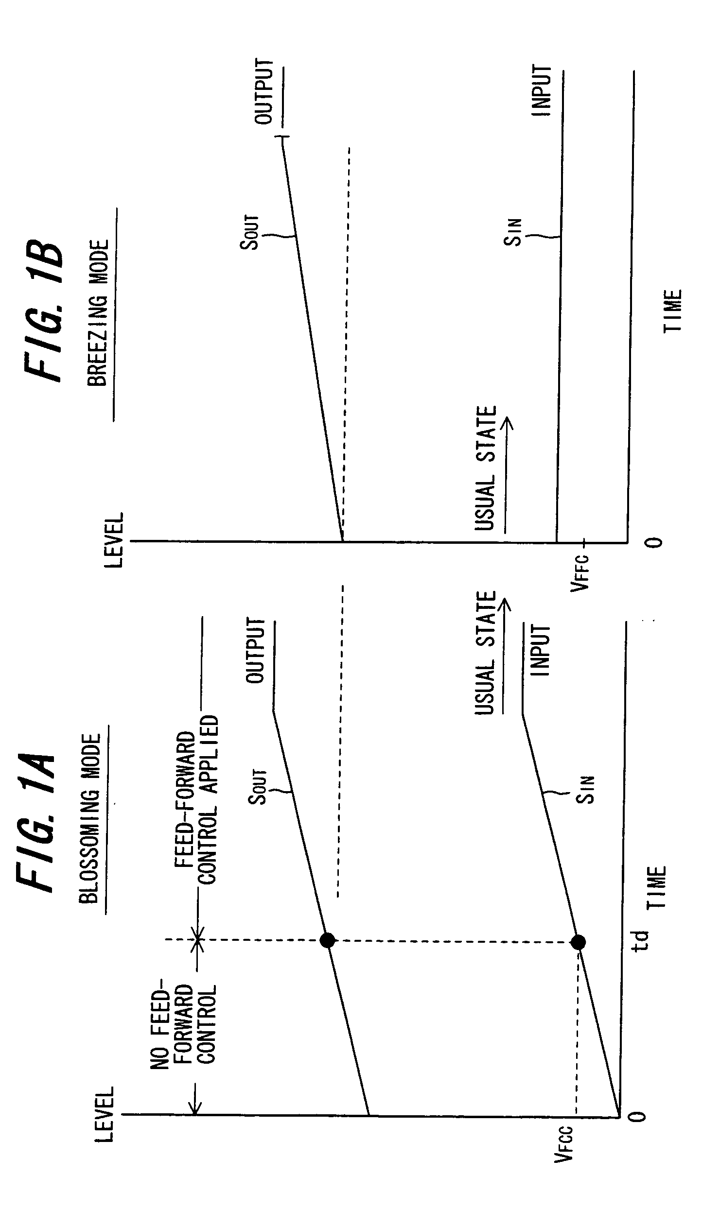
[0075] When the blossoming mode is in effect, there are instances where the input power SIN to the high-power amplifier fluctuates for some reason, as shown in FIG. 8. In such case the output power SOUT of the high-power amplifier also will fluctuate in the manner indicated, the transmission power of the base station will no longer vary linearly with respect to time and it will no longer be possible to exercise the original power control that attempts to enlarge the cell (the transmission area) gradually in proportion to time. Accordingly, it is necessary to control the transmission power of the base station in the manner indicated by the dashed line SIDL.

[0076]FIG. 9 is a diagram showing the structure of a high-power amplifier according to a third embodiment for controlling transmission power linearly with respect to a non-linear input. Components identical with those of the second embodiment of FIG. 6 are designated by like reference characters. This embodimen...


PUM


Abstract

A transmission power amplifier unit of a base-station apparatus for compensating for non-linear distortion of a transmission power amplifier by feed-forward control is provided with a gain varying unit for varying gain of the transmission power amplifier unit. At start-up of the transmission power amplifier unit, a controller determines whether the base-station apparatus is in a blossoming mode or breathing mode, maximizes gain of the transmission power amplifier unit by controlling the gain varying unit if the mode is the blossoming mode and increases the gain gradually in proportion to the passage of time if the mode is the breathing mode.

Description

BACKGROUND OF THE INVENTION [0001] This invention relates to a transmission power amplifier unit and, more particularly, to a transmission power amplifier unit, which has a transmission power amplifier, for compensating for non-linear distortion of the transmission power amplifier by feed-forward control. [0002] Frequency resources have become tight in recent years and in wireless communications there is growing use of high-efficiency transmission using digital techniques. In instances where multilevel amplitude modulation is applied to wireless communications, a vital technique is one which can suppress non-linear distortion by linearizing the amplitude characteristic of the power amplifier on the transmitting side and reduce the leakage of power between adjacent channels. Also essential is a technique which compensates for the occurrence of distortion that arises when an attempt is made to improve power efficiency by using an amplifier that exhibits poor linearity. [0003]FIG. 12 i...

Claims


Application Information

Patent Timeline
Patent Type & Authority Applications(United States)
IPC IPC(8): H04B1/04H01Q11/12H04B1/38H04M1/00H04Q7/20H04B7/00H03F1/32H04W52/50H04W52/52H04W88/14
CPCH03F1/32H03F1/3229H03F1/3247H03F1/3282H04W52/52H03F2201/3233H03G3/3042H04B1/04H03F2200/105
Inventor SAITO, YUTAKAMATSUDA, AYANORI
Owner SAITO YUTAKA
Why Eureka
Try Eureka