Check patentability & draft patents in minutes with Patsnap Eureka AI!

Targeted optimization of buffer-tree logic

a buffer tree and logic technology, applied in the field of circuit design methodologies, can solve the problems of complex equations, time-consuming, attenuation of signal shape, and inability to optimize every signal path for an entire circuit, and achieve the effect of optimizing the network and reducing slack timing

Inactive Publication Date: 2006-02-23
IBM CORP
View PDF8 Cites 14 Cited by
  • Summary
  • Abstract
  • Description
  • Claims
  • Application Information

AI Technical Summary

Benefits of technology

[0012] One embodiment provides a method of optimizing an integrated circuit design. The method generally includes (a) identifying buffer trees existing in the network, (b) applying one or more selection criteria to the identified buffer trees, (c) building a list of buffer trees targeted for optimization comprising a limited subset of the identified buffer trees that satisfy the selection criteria, and (d) performing one or more buffer optimization algorithms on one or more of the targeted buffer trees in the list.
[0013] Another embodiment provides another method of optimizing an integrated circuit design. The method generally includes (a) identifying buffer trees existing in the network, (b) building a list of buffer trees to target for optimization by, for each identified buffer tree, (i) determining if an area of a wire topology of the buffer tree without buffers exceeds a specified threshold area and the buffer tree with buffers exhibits negative slack timing, and (ii) if so, adding the buffer tree to the list, and (c) performing one or more buffer optimization algorithms on one or more of the targeted buffer trees in the list.
[0014] Another embodiment provides a

Problems solved by technology

As an electrical signal travels along a physical wire, the shape of the signal can become attenuated over distance such that it is difficult (since the transition from one logic value to another takes longer) or even impossible for a receiving ASIC cell to detect a logic change in a signal that is propagated too far.
Accurate computations of propagation delay within a signal path, which are utilized in optimization algorithms to determine buffer locations, typically involve complex equations and can be time consuming.
As ASIC designs often have several million placeable ASIC cells, as well as several million interconnecting wires, optimizing every signal path for an entire circuit can be very time consuming, taking days or even weeks.
However, such optimizations may prove sub-optimal when cells are combined to produce the finished product, or a larger tree.

Method used


Image

  • Targeted optimization of buffer-tree logic
  • Targeted optimization of buffer-tree logic
  • Targeted optimization of buffer-tree logic

Examples


Embodiment Construction

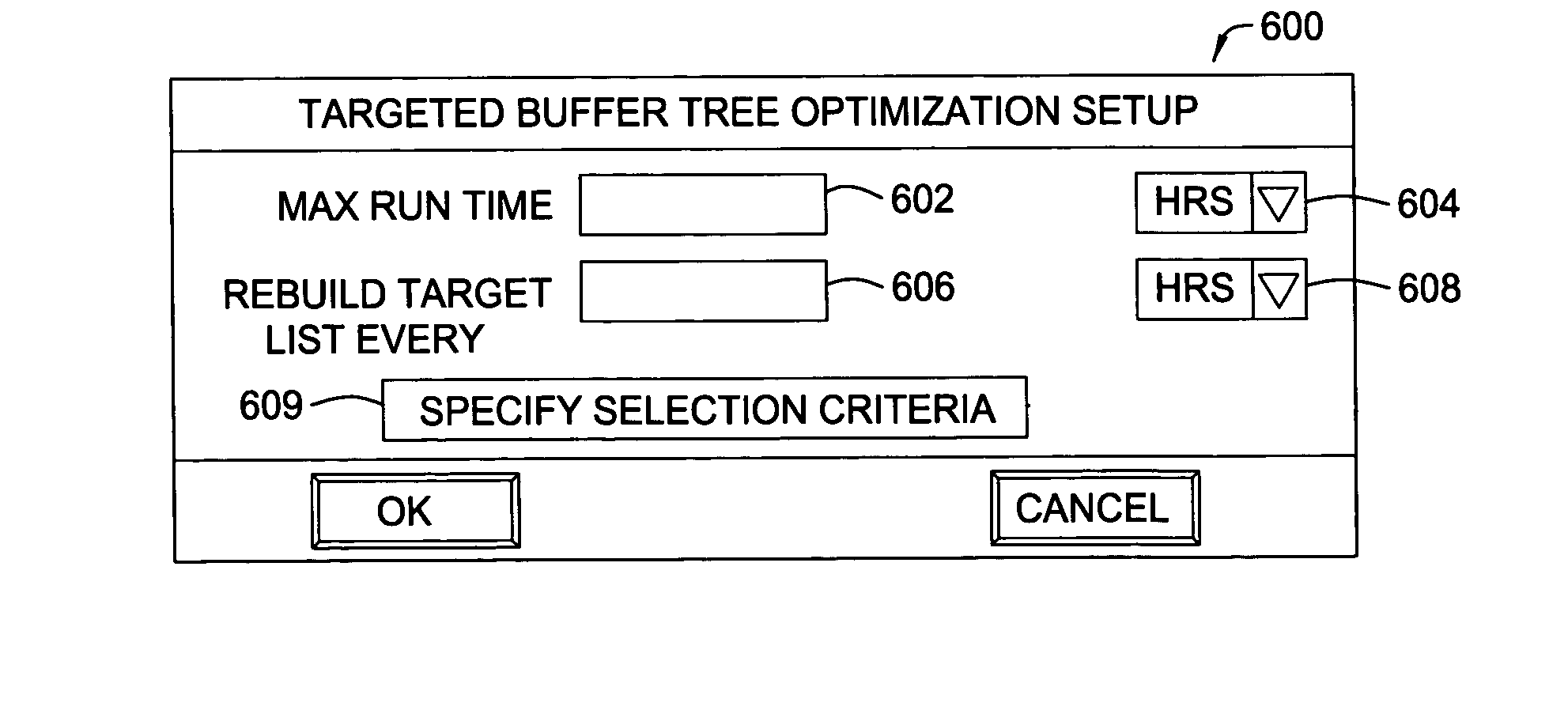
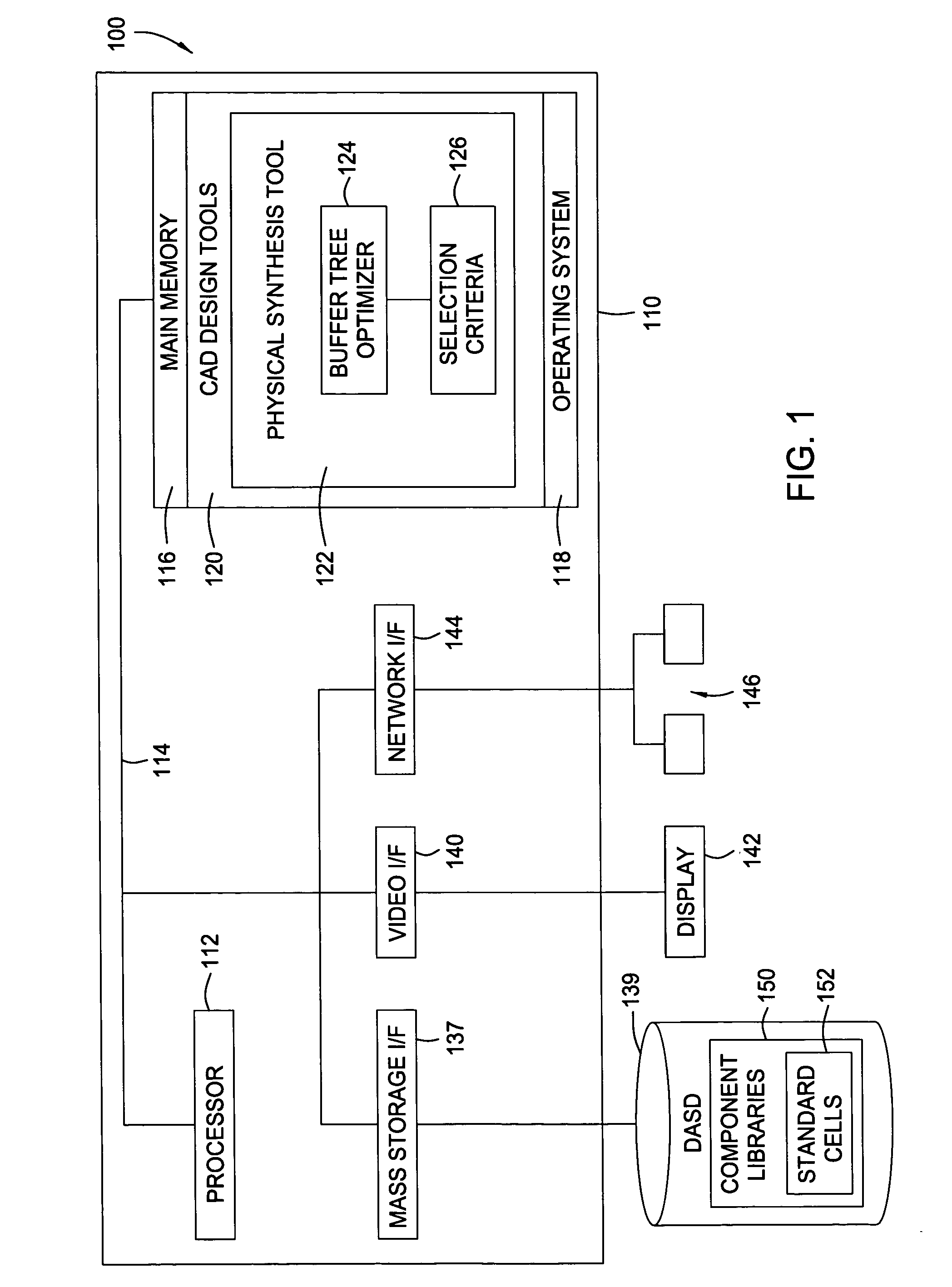
[0024] The present invention generally provides computationally efficient methods and systems for optimizing an integrated circuit (IC) design by targeting only a limited subsection of buffer trees in the network for optimization. By making intelligent decisions about which buffer trees to optimize, greater gains in design efficiency (e.g., as measured by reduced signal delays and / or wire length) may be realized at greatly reduced computational times when compared to conventional techniques that attempt to optimize each buffer tree.

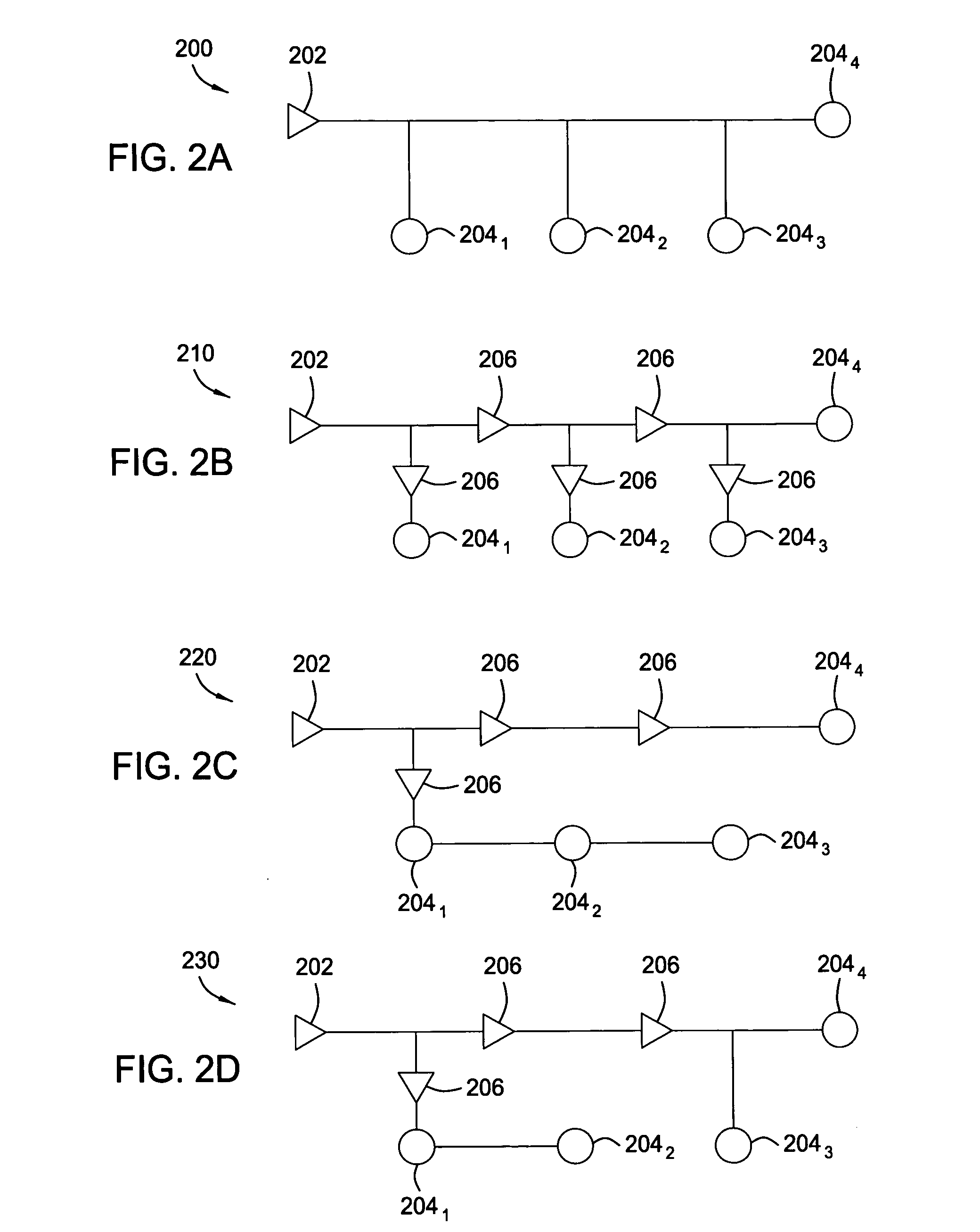
[0025] As used herein, the term buffer generally refers to any circuit device that may be used to assist in propagating a signal or an inverse of the signal. Accordingly, since non-inverting buffers are typically constructed of inverter pairs, the term buffer as used herein includes both non-inverting buffers and inverters. The term buffer tree generally refers to a collection of buffers located along signal paths between a common source node (a source) ...


PUM


Abstract

Computationally efficient methods and systems for optimizing an integrated circuit (IC) design by targeting only a limited subsection of buffer trees in the buffer system for optimization are provided. By making intelligent decisions about which buffer trees to optimize, greater gains in design efficiency (e.g., as measured by reduced delays and / or wire length) may be realized at greatly reduced computational times when compared to conventional techniques that attempt to optimize each buffer tree.

Description

CROSS-REFERENCE TO RELATED APPLICATIONS [0001] The present application is related to commonly-owned U.S. Pat. No. 6,044,209, entitled “Method And System For Segmenting Wires Prior to Buffer Insertion”, and U.S. Pat. No. 6,591,411, entitled “Apparatus And Method For Determining Buffered Steiner Trees For Complex Circuits,” each incorporated herein in their entirety.BACKGROUND OF THE INVENTION [0002] 1. Field of the Invention [0003] The present invention generally relates to circuit design methodologies and, more particularly, to improved buffer tree logic design and optimization. [0004] 2. Description of the Related Art [0005] A prevalent method of digital logic design is the Application Specific Integrated Circuit (ASIC) design method. The ASIC design approach abstracts individual transistor configurations that perform certain logic functions (such as a two input “nand”) into what is referred to as a “standard cell.” A library of standard cells is typically created and provided by a...

Claims


Application Information

Patent Timeline
IPC IPC(8): G06F17/50G06F9/45
CPCG06F2217/84G06F17/505G06F30/327G06F2119/12
Inventor DRUMM, ANTHONY DEGROFFWILSON, BRIAN CHRISTOPHER
Owner IBM CORP
Features
  • R&D
  • Intellectual Property
  • Life Sciences
  • Materials
  • Tech Scout
  • Unparalleled Data Quality
  • Higher Quality Content
  • 60% Fewer Hallucinations
Learn More