System and method for detecting decreased performance in a refrigeration system

a technology of a refrigeration system and a detection method, which is applied in the field of system and method for detecting performance degradation in a refrigeration system, can solve the problems of system components degradation, leakage of refrigerant, and the degradation of system performance, so as to avoid downtime, reduce subcooling, and avoid inefficient operation.

Inactive Publication Date: 2006-03-02
YORK INT
View PDF25 Cites 115 Cited by
  • Summary
  • Abstract
  • Description
  • Claims
  • Application Information

AI Technical Summary

Benefits of technology

[0008] One advantage of the present invention is that low refrigerant charge can be detected at a very early stage, allowing for repair of the system to fix the leak to avoid downtime, as well as potential damage to the system and its components.
[0009] Another advantage of the present invention is that degradation of the condenser and associated component and system performance can be detected at a very early stage, allowing for maintenance and repair to restore condenser and component performance to avoid inefficient operation due to decreased subcooling, as well as possible damage to the system and its components.
[0010] Yet another advantage is that the invention promotes more efficient operation of refrigeration systems by permitting early detection and repair of low refrigerant charge and condenser problems.
[0011] Other features and advantages of the present invention will be apparent from the following more detailed description of the preferred embodiment, taken in conjunction with the accompanying drawings which illustrate, by way of example, the principles of the invention.

Problems solved by technology

Compression refrigeration systems, including refrigeration, HVAC, and air conditioning systems (collectively hereinafter “refrigeration”) may encounter degradation of performance resulting from the degradation of system components.
For example, degradation of seals, piping, and component connections can lead to leakage of refrigerant.
In addition to undesirable environmental hazards posed by refrigerant leakage, system performance and efficiency rapidly deteriorates from low refrigerant charge, resulting in energy inefficiency, as well as potential system shutdown and possible damage to system components.
With respect to refrigeration systems employing condensers, degradation can occur as a result of a variety of factors such as debris blocking the airflow to the condenser coil, non-condensables in the condenser, and condenser fan malfunction.
Compressor degradation can result in an undesirable increase of condenser pressure over time, thereby adversely affecting system efficiency and performance.

Method used


Image

  • System and method for detecting decreased performance in a refrigeration system
  • System and method for detecting decreased performance in a refrigeration system
  • System and method for detecting decreased performance in a refrigeration system

Examples


Embodiment Construction

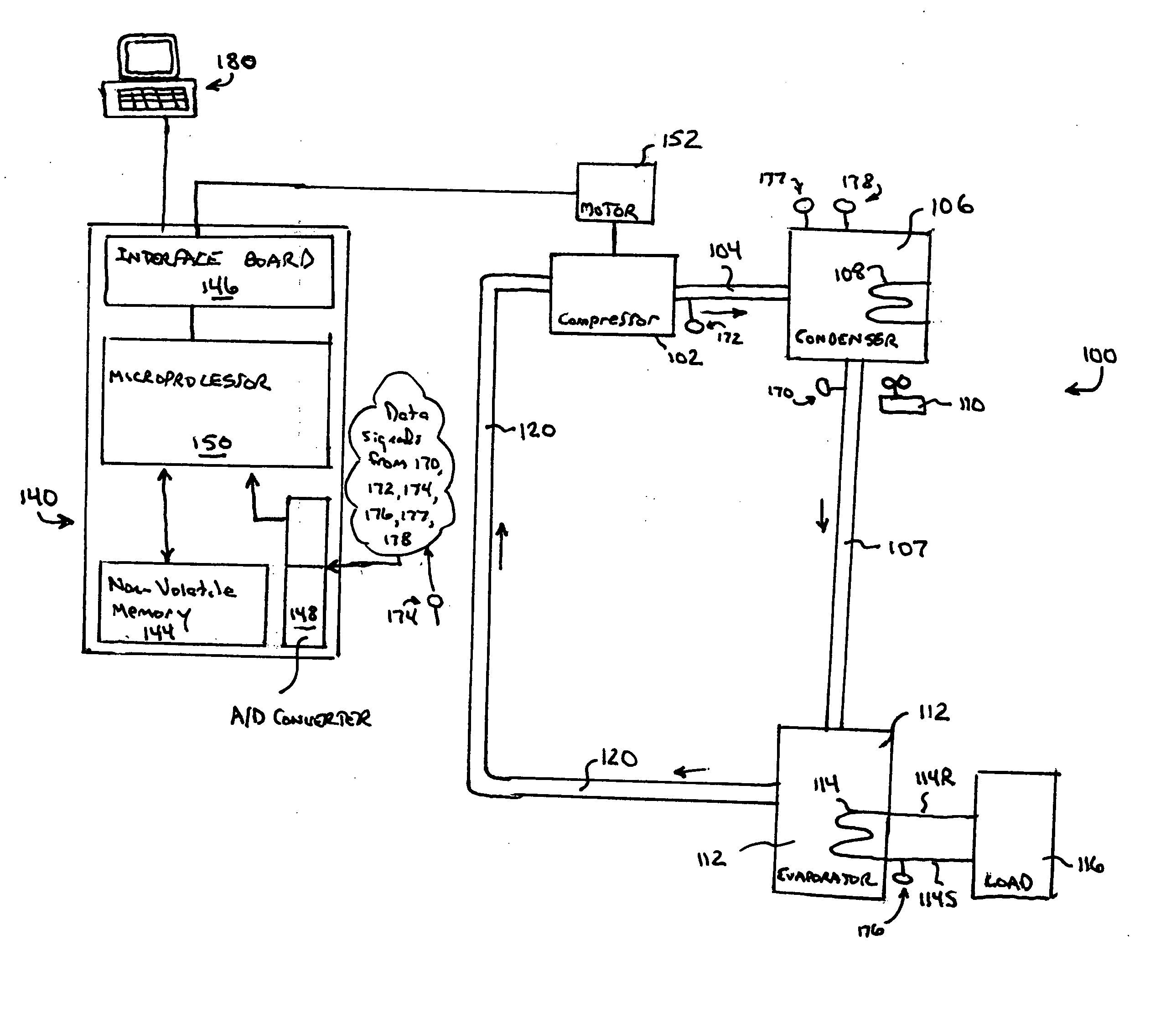
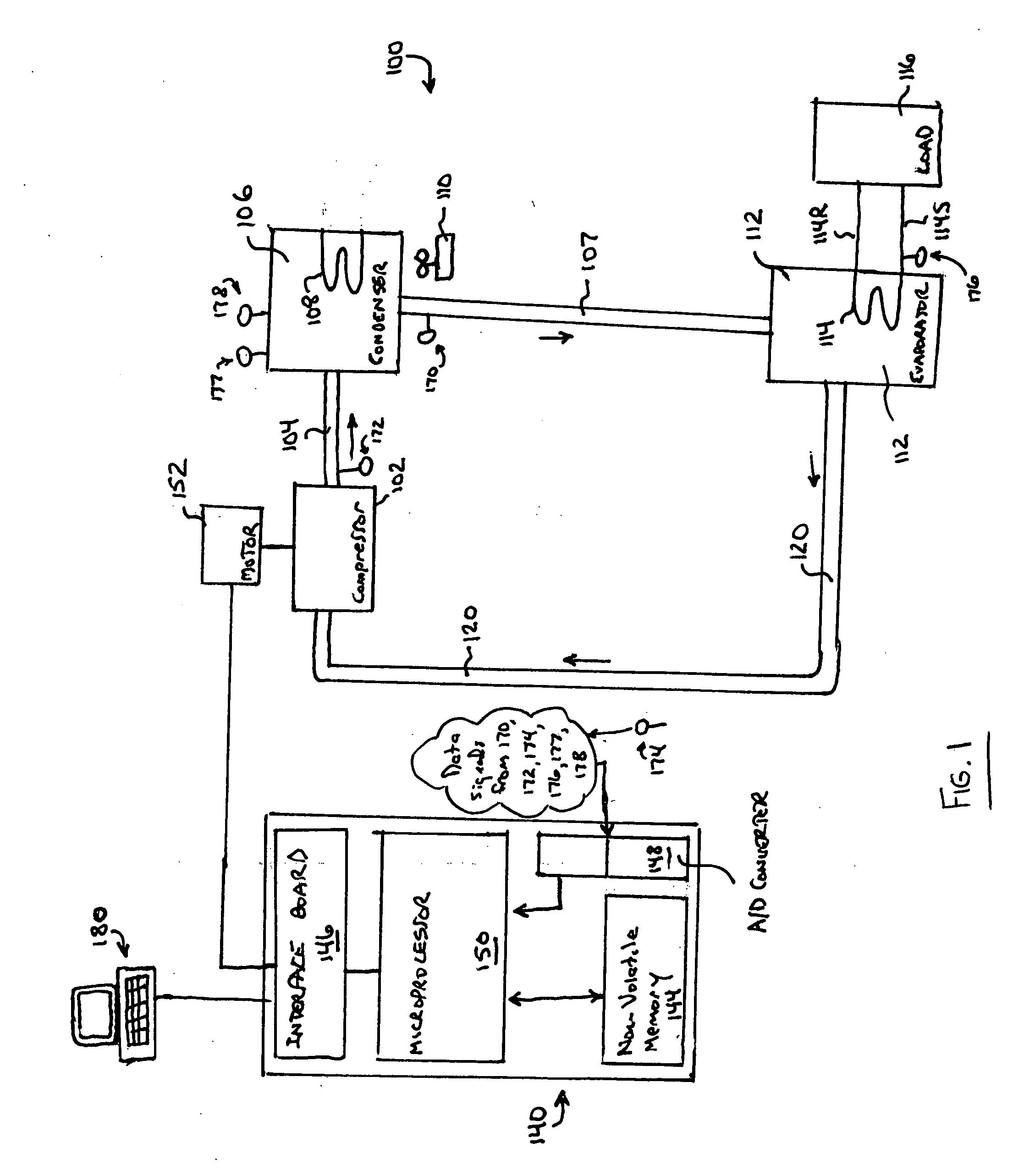
[0016] A general system to which the invention can be applied is illustrated, by means of example, in FIG. 1. As shown, the system 100, whether an HVAC, refrigeration, or liquid chiller system, includes a compressor 102, a condenser 106, a water chiller or evaporator 112, and a control panel 140. The control panel 140 can include an analog to digital (A / D) converter 148, a microprocessor 150, a non-volatile memory 144, and an interface board 146. The features and operation of the control panel 140 will be discussed in greater detail below. The conventional liquid chiller system 100 includes many other features that are not shown in FIG. 1. These features have been purposely omitted to simplify the drawing for ease of illustration.

[0017] Compressor 102 compresses a refrigerant vapor and delivers the vapor to the condenser 106 through a discharge line 104. The compressor 102 is preferably a centrifugal compressor, although other types of compressors including screw, scroll, and recip...


PUM

PropertyMeasurementUnit
temperatureaaaaaaaaaa
discharge pressureaaaaaaaaaa
condensing pressureaaaaaaaaaa

Abstract

Systems and methods are provided for detecting performance degradation in a refrigeration system. Specifically, the present invention provides systems and methods for detecting, at a very early stage, a low refrigerant charge and degradation in condenser performance of a refrigeration system.

Description

BACKGROUND OF THE INVENTION [0001] The present invention relates generally to a system and method for detecting performance degradation in a refrigeration system. More specifically, the present invention relates to systems and methods for detecting, at a very early stage, a low refrigerant charge and degradation in condenser performance of a refrigeration system. [0002] Compression refrigeration systems, including refrigeration, HVAC, and air conditioning systems (collectively hereinafter “refrigeration”) may encounter degradation of performance resulting from the degradation of system components. For example, degradation of seals, piping, and component connections can lead to leakage of refrigerant. In addition to undesirable environmental hazards posed by refrigerant leakage, system performance and efficiency rapidly deteriorates from low refrigerant charge, resulting in energy inefficiency, as well as potential system shutdown and possible damage to system components. With respec...

Claims


Application Information

Patent Timeline
Patent Type & Authority Applications(United States)
IPC IPC(8): G01K13/00F25D17/02F25B15/00
CPCF25B49/005F25B2600/19F25B2700/04F25B2700/21173F25B2700/195F25B2700/2106F25B2700/21163F25B2700/1931F25B49/00F25B49/02G05B23/02
Inventor DOLL, MARTIN LUTHER JR.HANSEN, JOHN C.
Owner YORK INT
Why Eureka
Try Eureka