Fuel injection apparatus including device for suppressing pressure waves in reservoir injection systems

Inactive Publication Date: 2006-03-02
ROBERT BOSCH GMBH
View PDF13 Cites 17 Cited by
  • Summary
  • Abstract
  • Description
  • Claims
  • Application Information

AI Technical Summary

Benefits of technology

[0005] With the compensation device proposed according to the invention between a high-pressure reservoir and a fuel injector, the pressure fluctuations that occur when fuel is withdrawn from the high-pressure reservoir can be reduced. The compensation device eliminates a pressure disappearance that occurs at the onset of an injection event, and it prevents a pressure drop both during injection and in injection phases that follow the injection. The injection pressure and the system efficiency of the fuel injection system are unimpaired by the compensation device. Upon triggering of a pressure booster of a fuel injector, or triggering of a fuel injector, the abrupt withdrawal of a quan

Problems solved by technology

This superelevation of pressure is chronologically limited, however, and decreases again toward the end of the injection phase.
Particularly in self-igniting internal co

Method used


Image

  • Fuel injection apparatus including device for suppressing pressure waves in reservoir injection systems
  • Fuel injection apparatus including device for suppressing pressure waves in reservoir injection systems
  • Fuel injection apparatus including device for suppressing pressure waves in reservoir injection systems

Examples


Embodiment Construction

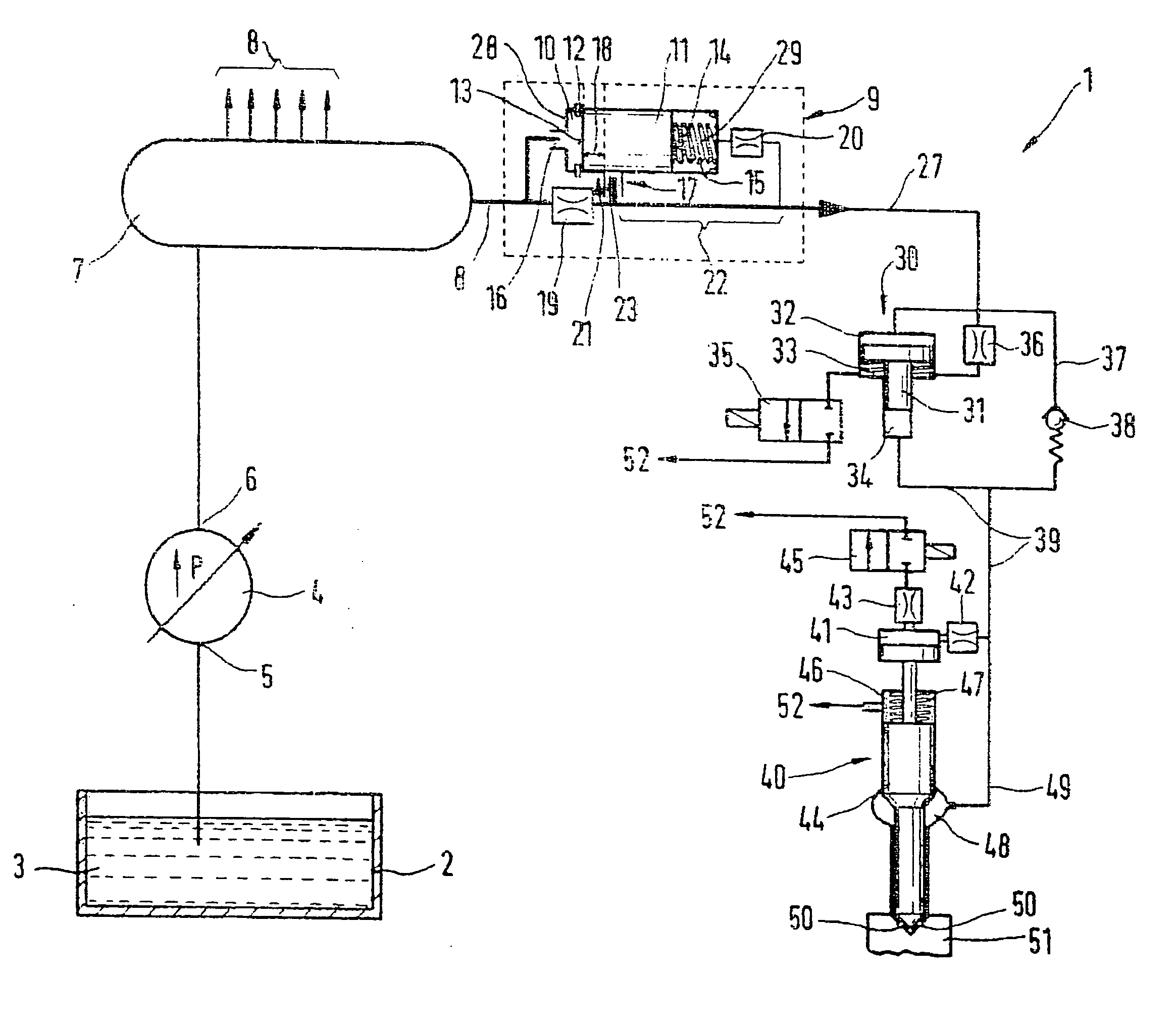
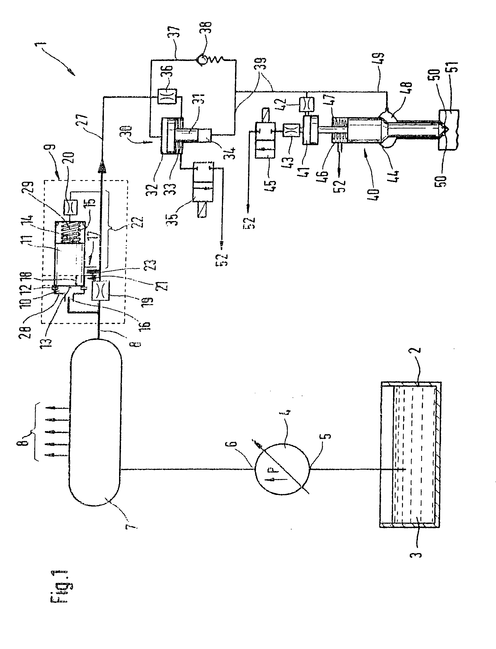
[0011]FIG. 1 shows a first variant embodiment of the compensation device proposed according to the invention, in which the throttle restrictions are located outside the compensation device.

[0012] In the first exemplary embodiment of the fuel apparatus of the invention shown in FIG. 1, a fuel injection system 1 includes a fuel tank 2, which is filled with fuel 3. From the fuel tank 2, the fuel 3 is pumped via a fuel pump 4. The fuel 3 enters the fuel pump 4 at a low-pressure side 5 and leaves the fuel pump 4 at a high-pressure side 6. By means of the fuel pump 4, the fuel 3 is delivered to a high-pressure reservoir 7 (common rail), in which fuel pressures of up to 16 bar prevail. On the outside of the high-pressure reservoir 7, high-pressure line connections 8 are located, in a number corresponding to the number of cylinders of the self-igniting engine to be supplied with fuel. Via each of the high-pressure connections 8 schematically shown in FIG. 1, fuel at high pressure is delive...


PUM


Abstract

A fuel injection apparatus has a pressure booster located between a high-pressure reservoir and a nozzle chamber. A high-pressure chamber of this fuel injection apparatus communicates with the pressure line with a control chamber which actuates an injection valve member of a fuel injector and with the nozzle chamber. A compensation device is connected to a high-pressure line between the high-pressure reservoir and the fuel injector produces a throttled connection or an unthrottled connection between the high-pressure reservoir and the fuel injector.

Description

FIELD OF THE INVENTION [0001] Both pressure-controlled and stroke-controlled injection systems can be used to supply fuel to combustion chambers of self-igniting internal combustion engines. Besides unit fuel injectors and pump-line units, reservoir injection systems (common rails) are also used. Common rails advantageously make it possible for instance to adapt the injection pressure to the load and rpm of the engine. To achieve high specific outputs and to reduce emissions, the highest possible injection pressure is generally required. BACKGROUND OF THE INVENTION [0002] For reasons of strength, the attainable pressure level in reservoir injection systems (common rails) in current use is at present limited to about 1800 bar. To further increase the pressure in reservoir injection systems, a pressure booster can be used in common rail systems. [0003] German Patent Disclosure DE 199 10 970 A1 discloses a fuel injection apparatus. The fuel injection apparatus has a booster unit, locat...

Claims


Application Information

Patent Timeline
IPC IPC(8): F02M57/02F02M47/02F02M55/00F02M55/04F02M59/10F02M63/00F02M63/02
CPCF02M47/027F02M55/00F02M55/04F02M2200/40F02M59/105F02M63/0225F02M2200/315F02M57/025
Inventor MAGEL, HANS-CHRISTOPH
Owner ROBERT BOSCH GMBH
Why Eureka
Try Eureka