Plasma etching apparatus

a technology of etching apparatus and plasma, which is applied in the direction of electrical apparatus, basic electric elements, electric discharge tubes, etc., can solve the problems of difficult control of etching characteristics, difficult to realize uniform etching, and portion of the substrate, so as to achieve the effect of improving etching characteristics

Inactive Publication Date: 2006-03-02
TOKYO ELECTRON LTD
View PDF7 Cites 124 Cited by
  • Summary
  • Abstract
  • Description
  • Claims
  • Application Information

AI Technical Summary

Benefits of technology

[0005] It is, therefore, an object of the present invention to provide a parallel plate plasma etching apparatus capable of improving a controllability of etching characteristics by way of precisely and freely controlling a flow or a density distribution of a processing gas introduced into a processing chamber.
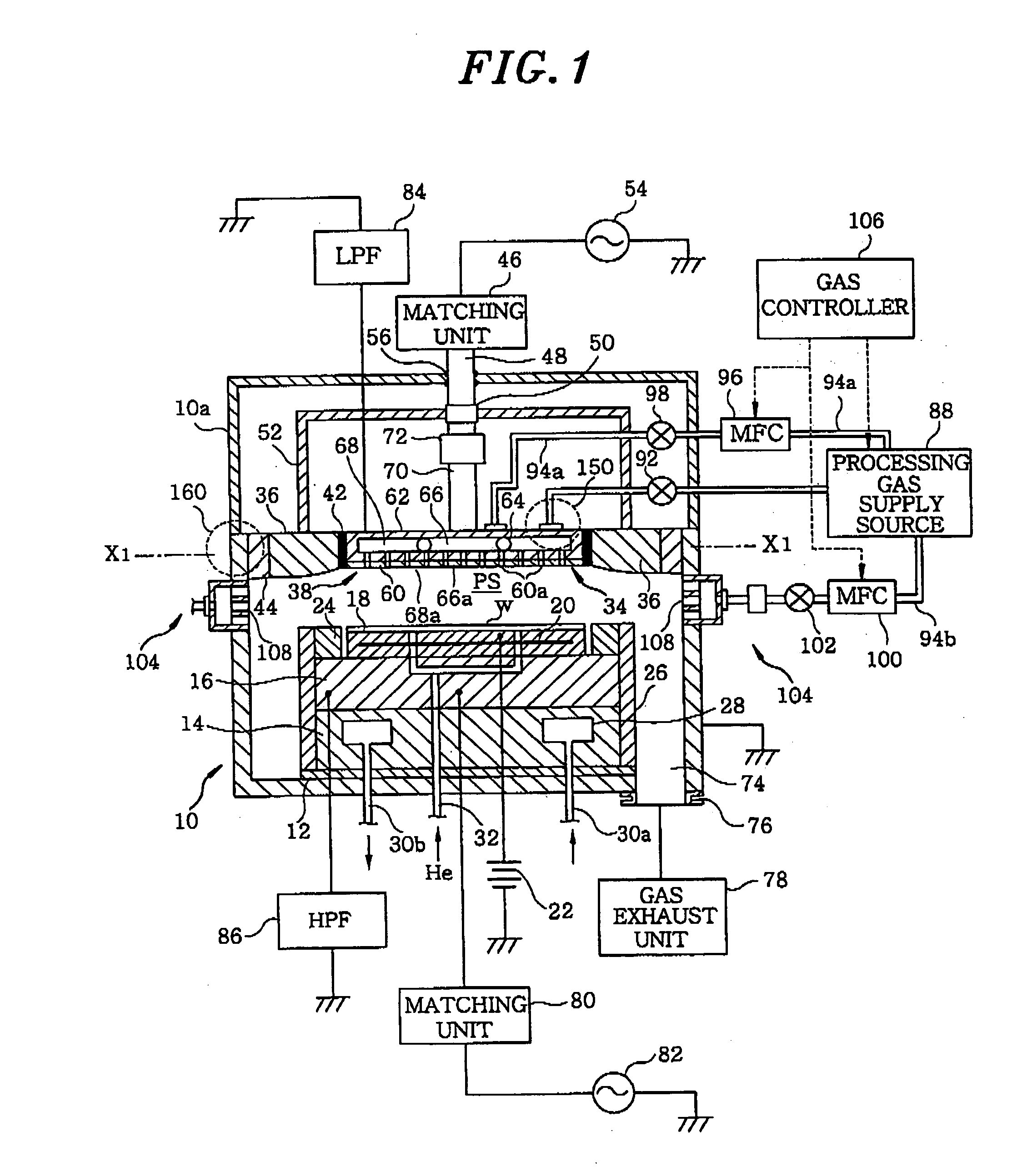
[0007] In the first plasma etching apparatus, the first gas including etchant gas is introduced downward through the upper gas inlet into the plasma generation region between the upper electrode and the lower electrode and, at the same time, the second gas including dilution gas is introduced inwardly through the side gas inlet into the plasma generation region. In accordance with such gas introduction manner for introducing and mixing different etching gas species from two directions of the upper and the side portion, gas species, gas mixing ratios and gas flow rates of each system can be properly selected and adjusted and, further, a balance between both systems can be controlled. Accordingly, it is possible to precisely and freely control a flow or a density distribution of a processing gas in the plasma generation region, thereby improving a controllability of etching characteristics on a substrate.
[0014] In the second plasma etching apparatus, the first gas including dilution gas is introduced downward through the upper central gas inlet into the plasma generation region between the upper electrode and the lower electrode; the second gas including etchant gas is introduced downward through the upper peripheral gas inlet into the plasma generation region; and the third gas including dilution gas is introduced inwardly (toward the center) through the side gas inlet. In accordance with such gas introduction manner for introducing two gas species for etching from two directions, i.e., from above and side and mixing the first and the third gas including dilution gas respectively through the upper central gas inlet and the side gas inlet so that the second gas including etchant gas introduced through the upper peripheral gas inlet can be maintained between the central portion and the side portion, it is possible to precisely and freely control a flow or a density distribution of a processing gas in the plasma generation region. Accordingly, a controllability of etching characteristics on a substrate can be further enhanced.
[0020] In the third plasma etching apparatus, the first gas including dilution gas is introduced downward through the first upper gas inlet into the plasma generation region between the upper electrode and the lower electrode; the second gas including etchant gas is introduced downward through the second upper gas inlet into the plasma generation region; and the third gas including dilution gas is introduced downward through the third gas inlet into the plasma generation region. In accordance with such gas introduction manner for introducing and mixing the first and the third gas including dilution gas respectively through the first and the third upper gas inlet so that the second gas including etchant gas introduced through the second upper gas inlet located at a middle portion of the upper electrode in a diametric direction, can be maintained between the central portion and the peripheral portion, it is possible to precisely and freely control a flow or a density distribution of a processing gas in the plasma generation region. Accordingly, a controllability of etching characteristics on a substrate can be further improved.
[0025] In accordance with the plasma etching apparatus of the present invention, by the aforementioned configuration and operation, it is possible to precisely and freely control a flow or a density distribution of a processing gas introduced into a processing chamber, so that etching characteristics can be improved.

Problems solved by technology

However, in the conventional parallel plate plasma etching apparatus, it is difficult to realize uniform etching characteristics on a substrate to be processed and, further, it is hard to control etching characteristics, especially on a peripheral portion of the substrate.

Method used


Image

  • Plasma etching apparatus
  • Plasma etching apparatus
  • Plasma etching apparatus

Examples


first embodiment

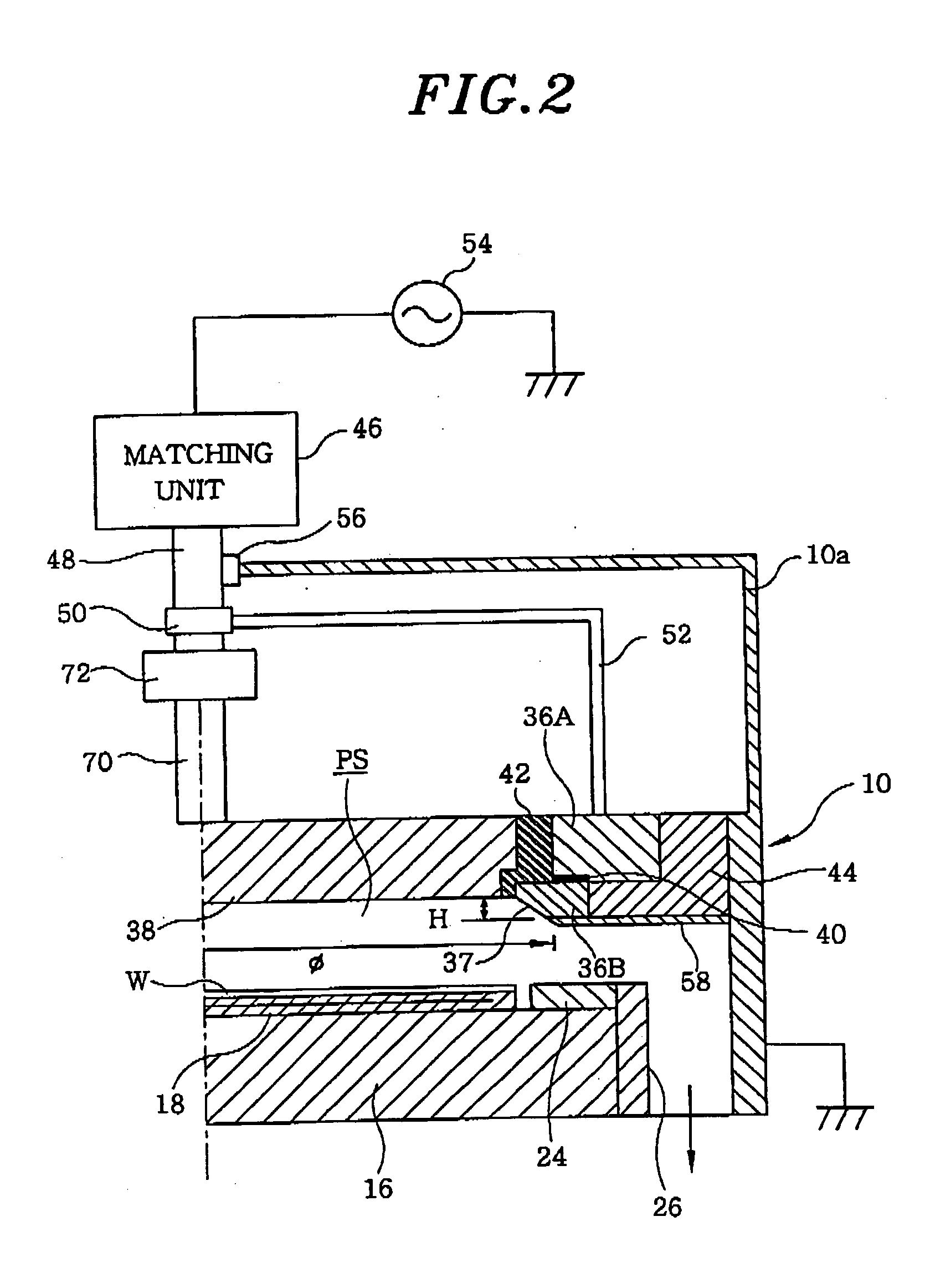
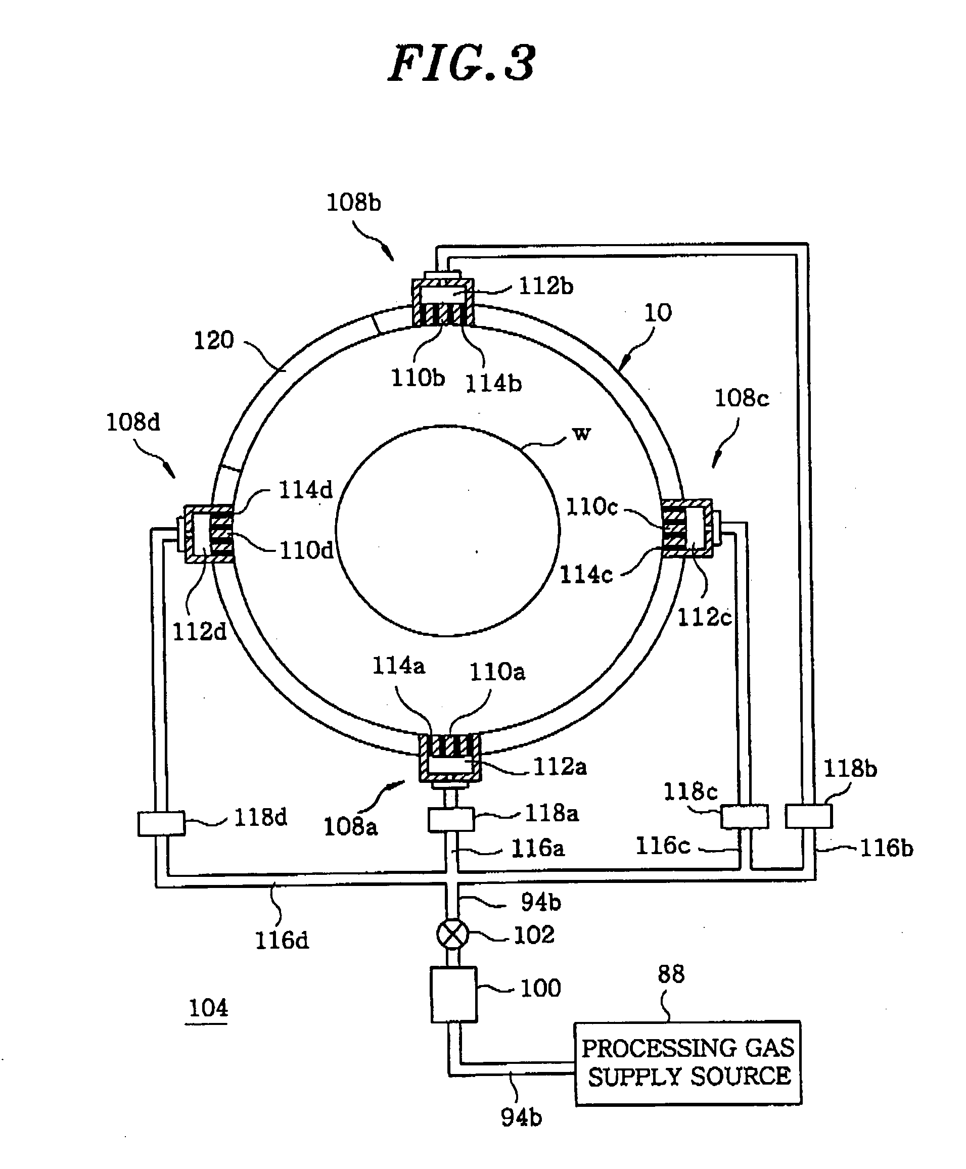
[0079] Hereinafter, there will be described a gas introduction mechanism for introducing a processing gas (etching gas) into the chamber 10 in the plasma etching apparatus. Major features of the gas introduction mechanism in the first embodiment will be described as follows. As a gas inlet for introducing an etching gas into the plasma generation region PS in the chamber 10, there are provided an upper gas inlet (the upper central shower head 66a and the upper peripheral shower head 68a) for introducing a gas through the upper electrode 38 side and a side gas inlet 104 for introducing a gas through the sidewall side of the chamber 10. As illustrated in FIG. 1, the side gas inlet 104 has a side shower head 108 attached to the sidewall of the chamber 10.

[0080] Referring to FIG. 1, a processing gas supply source 88 provides an etchant gas to a gas supply line 90 at a desired flow rate and a dilution gas to a gas supply line 94 at a desired flow rate. The gas supply line 90 communicate...

second embodiment

[0107] Hereinafter, a gas introduction mechanism of a second preferred embodiment, for introducing a processing gas (an etching gas) into the chamber 10 in the plasma etching apparatus, will be described with reference to FIGS. 9 to 11. A major feature of the gas introduction mechanism in accordance with the second preferred embodiment is that instead of the side gas inlet 104 in the first preferred embodiment, a third upper shower head is provided at an outer portion of the upper peripheral shower head 68a as a gas inlet for introducing an etching gas into the plasma generation region PS in the chamber 10. In other words, the gas introduction mechanism of the second preferred embodiment includes a first upper shower head (the upper central shower head of the first preferred embodiment), a second upper shower head (the upper peripheral shower head of the first preferred embodiment) and the third upper shower head, which are sequentially provided from the central portion of the upper...


PUM

PropertyMeasurementUnit
thicknessaaaaaaaaaa
diameteraaaaaaaaaa
pressureaaaaaaaaaa

Abstract

In order to improve a controllability of etching characteristics by way of precisely and freely controlling a flow or a density distribution of a processing gas introduced into a processing chamber, a plasma etching apparatus includes, as a gas inlet for introducing an etching gas into a plasma generation region PS in a chamber 10, an upper gas inlet (an upper central shower head 66a and an upper peripheral shower head 68a) for introducing a gas through an upper electrode 38; and a side gas inlet for introducing a gas through a sidewall of the chamber 10. The side gas inlet 104 has a side shower head 108 attached to the sidewall of the chamber 10.

Description

FIELD OF THE INVENTION [0001] The present invention relates to a plasma etching apparatus; and, more particularly, to a parallel plate plasma etching apparatus. BACKGROUND OF THE INVENTION [0002] A recent trend towards a miniaturized semiconductor device structure in design criteria intensifies a demand for processing a material to be etched in a cross sectional shape of a high-density pattern. Currently, in a plasma etching apparatus for use in manufacturing a semiconductor device or a flat panel display (FPD), a generation of high-density plasma is indispensable for a miniaturization of a semiconductor device structure or a high-rate etching process for a substrate to be processed (a semiconductor wafer, a glass substrate or the like). Accordingly, in a parallel plate plasma etching apparatus, in order to generate the high-density plasma, various investigations or trials have been attempted by way of increasing a frequency of a plasma exciting radio frequency RF from a conventiona...

Claims


Application Information

Patent Timeline
Patent Type & Authority Applications(United States)
IPC IPC(8): H01L21/306
CPCH01J37/32091H01L21/31116H01J37/32449H01J37/3244
Inventor YOSHIDA, RYOICHIYOSHIDA, TETSUOSAITO, MICHISHIGEWAKAKI, TOSHIKATSUAOYAMA, HAYATOOBI, AKIRASUZUKI, HIROSHI
Owner TOKYO ELECTRON LTD
Why Eureka
Try Eureka