Supercharge Your Innovation With Domain-Expert AI Agents!

Reverse osmosis water purification system

a water purification system and reverse osmosis technology, applied in the field of water purification art, can solve the problems that the first water flowing through the faucet may not be as fully filtered, and achieve the effect of minimizing waste water and increasing efficiency

Inactive Publication Date: 2006-03-02
JOULAKIAN MIKE
View PDF6 Cites 8 Cited by
  • Summary
  • Abstract
  • Description
  • Claims
  • Application Information

AI Technical Summary

Benefits of technology

[0018] Depending upon the placement of the activated charcoal, water from the municipality is fed into the reverse osmosis unit. As noted above, in one embodiment of the present invention, all of the water passes through the carbon cake and then into the semipermeable membrane in which embodiment all of the inlet water is treated by the charcoal. In another embodiment of the present invention the charcoal filter is placed at the product water tube so that only the water flowing from the product water tube is filtered by the charcoal filter. The municipal water supply is at a pressure, for example in the range of 40 to 80 pounds per square inch to provide the osmotic pressure to the reverse osmosis unit. As noted above, if the inlet water pressure is too low, a pump may be utilized to boost the inlet water pressure to a value sufficient for proper reverse osmosis operation. The flowing water through the membrane forces a portion thereof through the membrane and into the product water tube. The product water tube is connected directly to the faucet. As noted above, when the faucet is first turned on after a period of non use, the first water which would flow the faucet may not be as fully filtered because of migration of the waster through the membrane during the periods of non use. In preferred embodiments of the present invention, a flow control system is provided and includes a solenoid operated diverter valve arrangement to prevent the first flow of water from the product water tube entering the faucet and diverts the first flow of water into the water drain. After a very brief time interval, the diverter valve arrangement directs the water from the product water tube into the faucet for consumption. The unique flow control system of the present invention provides the increased efficiency to minimize the waste water.

Problems solved by technology

As noted above, when the faucet is first turned on after a period of non use, the first water which would flow the faucet may not be as fully filtered because of migration of the waster through the membrane during the periods of non use.

Method used


Image

  • Reverse osmosis water purification system
  • Reverse osmosis water purification system
  • Reverse osmosis water purification system

Examples


Embodiment Construction

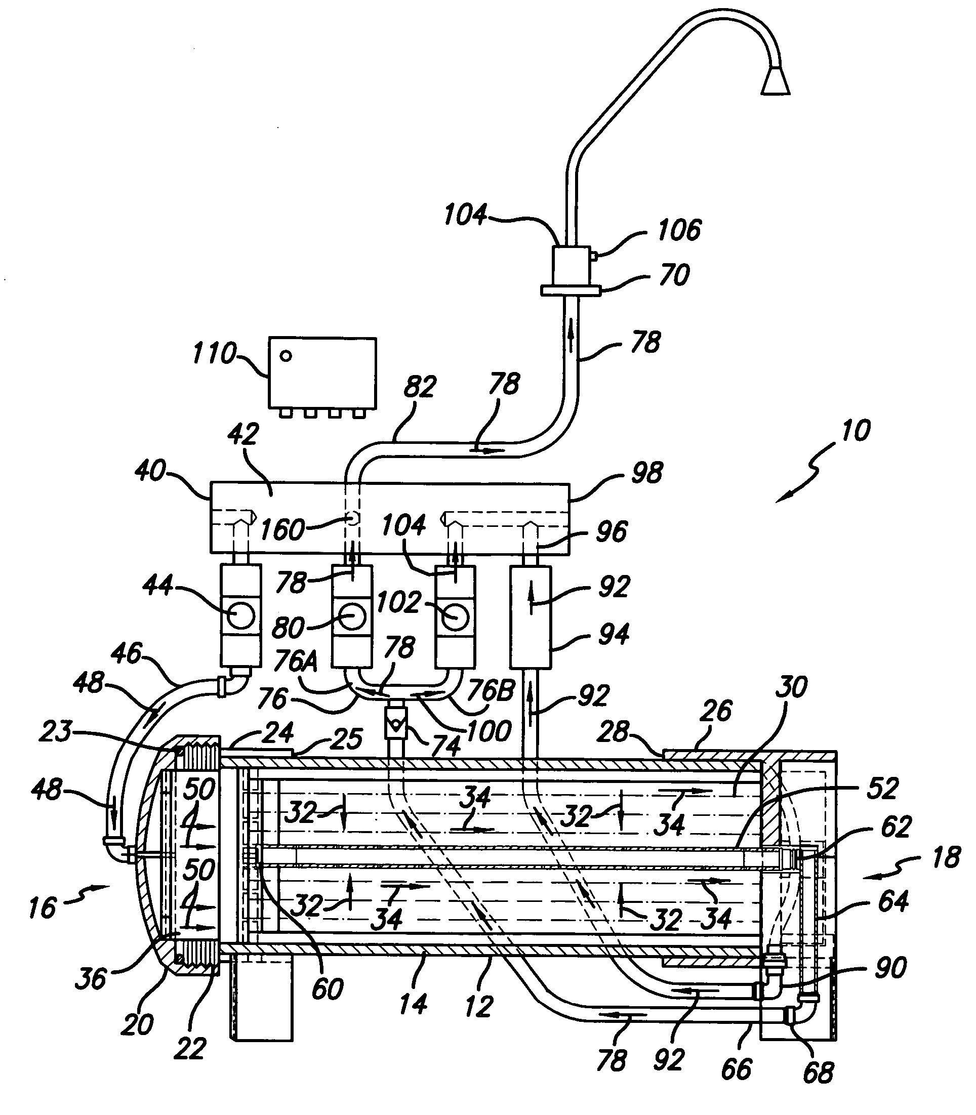
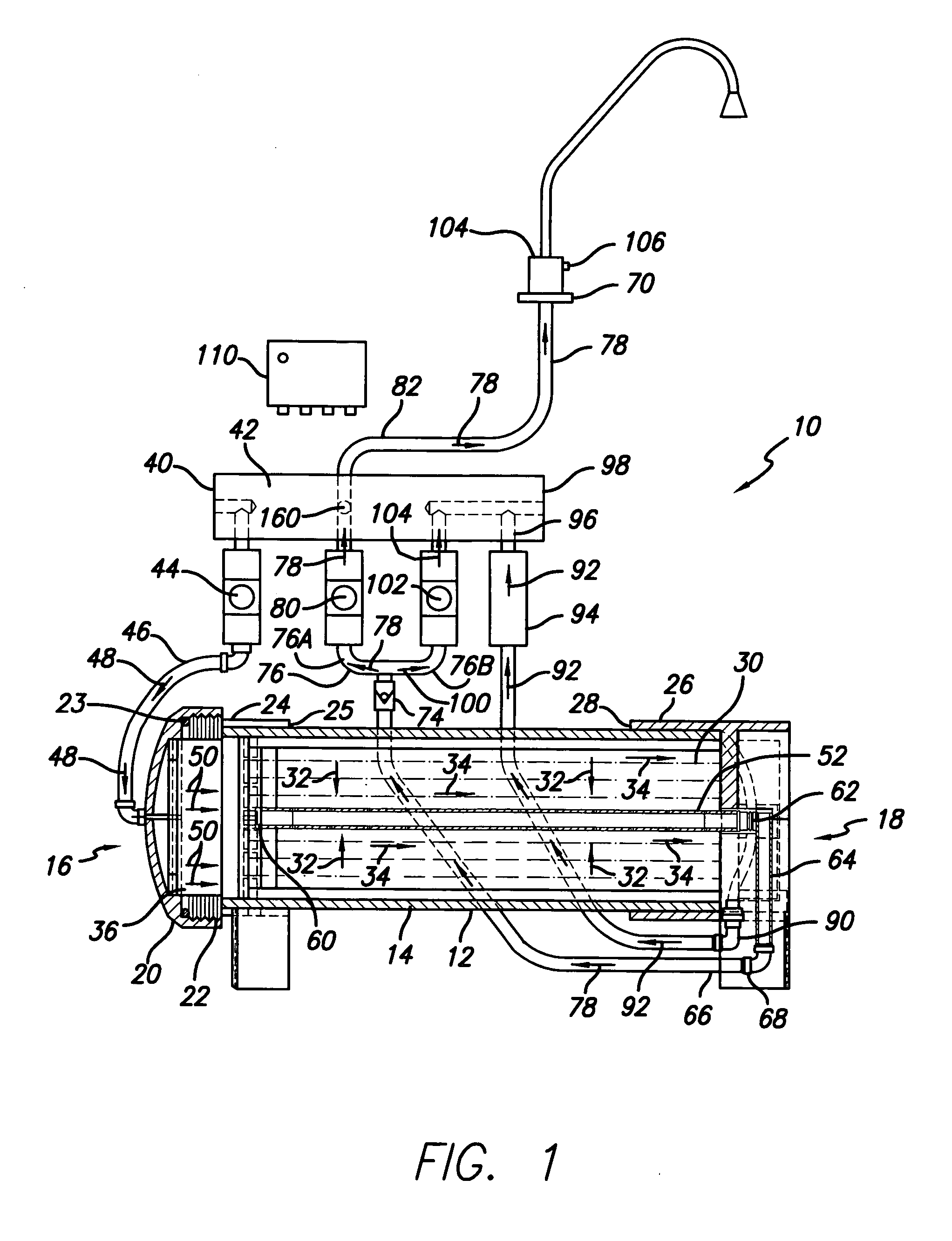
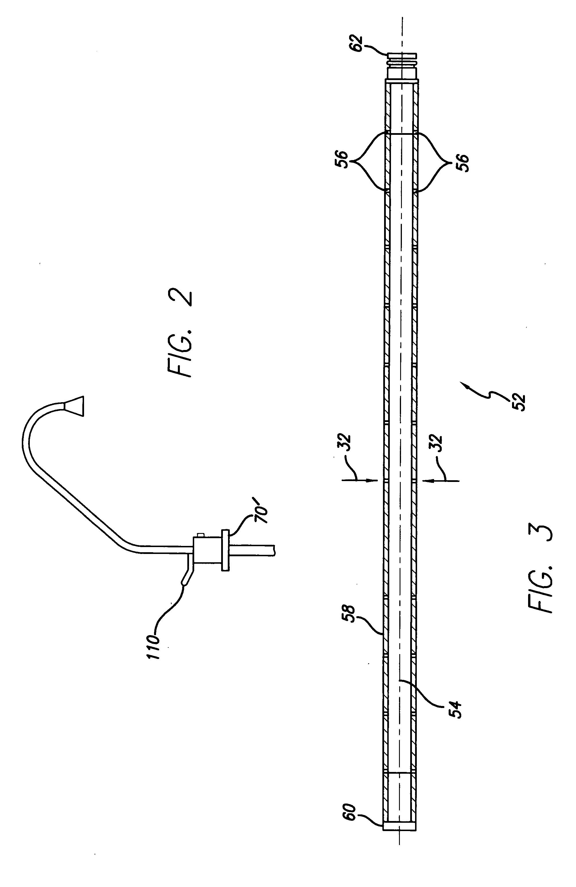
[0026] Referring now to the drawing there is illustrated on FIG. 1 a preferred embodiment of the present invention of a tankless, pumpless on demand reverse osmosis water purification system generally designated 10. The embodiment 10 has a pressure vessel 12 comprised of a generally tubular body member 14, an inlet end 16 and a discharge end 18. The inlet end 16 has an inlet end cap 20 that is threadingly coupled to the body member 14 as indicated at 22 through an adapter 24 that is fixedly coupled to the body member 14 as indicated at 25. An “O” ring 23 may be provided between the adapter 24 and the inlet end cap 20 to provide a sealing engagement therebetween.

[0027] The discharge end 18 has a discharge end cap 26 that is fixedly coupled to the body member 14 as indicated at 28. As assembled as shown on FIG. 1, the pressure vessel 12 is designed to withstand for continuous operation the operating pressure of the water supplied thereto which, for example, may be on the order of 40 ...


PUM

PropertyMeasurementUnit
pressuresaaaaaaaaaa
pressureaaaaaaaaaa
pressureaaaaaaaaaa

Abstract

A tankless, pumpless on demand reverse osmosis water purification system with provisions for flushing water from the product water tube and water supply line to the faucet which water is not the fully purified water provided by the reverse osmosis action before allowing the dispensing of the reverse osmosis purified water.

Description

BACKGROUND OF THE INVENTION [0001] 1. Field of the Invention [0002] This invention relates to the water purification art and more particularly to a tankless, pumpless on-demand reverse osmosis water purification system [0003] 2. Description of the Prior Art [0004] Over the years there has been an increasing pollution of the water supplies utilized for human consumption, and as populations increase worldwide there is expected to be an accompanying greater amount of pollutants produced which find their way into the water supply. Many of the pollutants are the result of the societal technological advancements and industrial activities which produce more products for human use but also produce more waste products. These waste products may include many toxic contaminants as well as unpleasant or undesired particulate materials which contaminate the aquifers and the water supplies. Such pollution of the water supply has caused many people to install water purification systems in their res...

Claims


Application Information

Patent Timeline
Patent Type & Authority Applications(United States)
IPC IPC(8): B01D61/12
CPCB01D61/08C02F1/441B01D61/12B01D61/10B01D61/081
Inventor JOULAKIAN, MIKE
Owner JOULAKIAN MIKE
Features
  • R&D
  • Intellectual Property
  • Life Sciences
  • Materials
  • Tech Scout
  • Unparalleled Data Quality
  • Higher Quality Content
  • 60% Fewer Hallucinations
Learn More