RFID device with combined reactive coupler

a technology of reactive couplers and rfid devices, which is applied in the direction of burglar alarm mechanical actuation, burglar alarm by hand-portable article removal, instruments, etc., can solve the problems of large area reducing the accuracy required for ic placement during manufacture, and serious limitations in high-speed manufacturing of ic placement and mounting

Active Publication Date: 2006-03-02
AVERY DENNISON CORP
View PDF16 Cites 191 Cited by
  • Summary
  • Abstract
  • Description
  • Claims
  • Application Information

AI Technical Summary

Problems solved by technology

The larger area reduces the accuracy required for placement of ICs during manufacture while still providing effective electrical connection.
IC placement and mounting are serious limitations for hig...

Method used


Image

  • RFID device with combined reactive coupler
  • RFID device with combined reactive coupler
  • RFID device with combined reactive coupler

Examples


Embodiment Construction

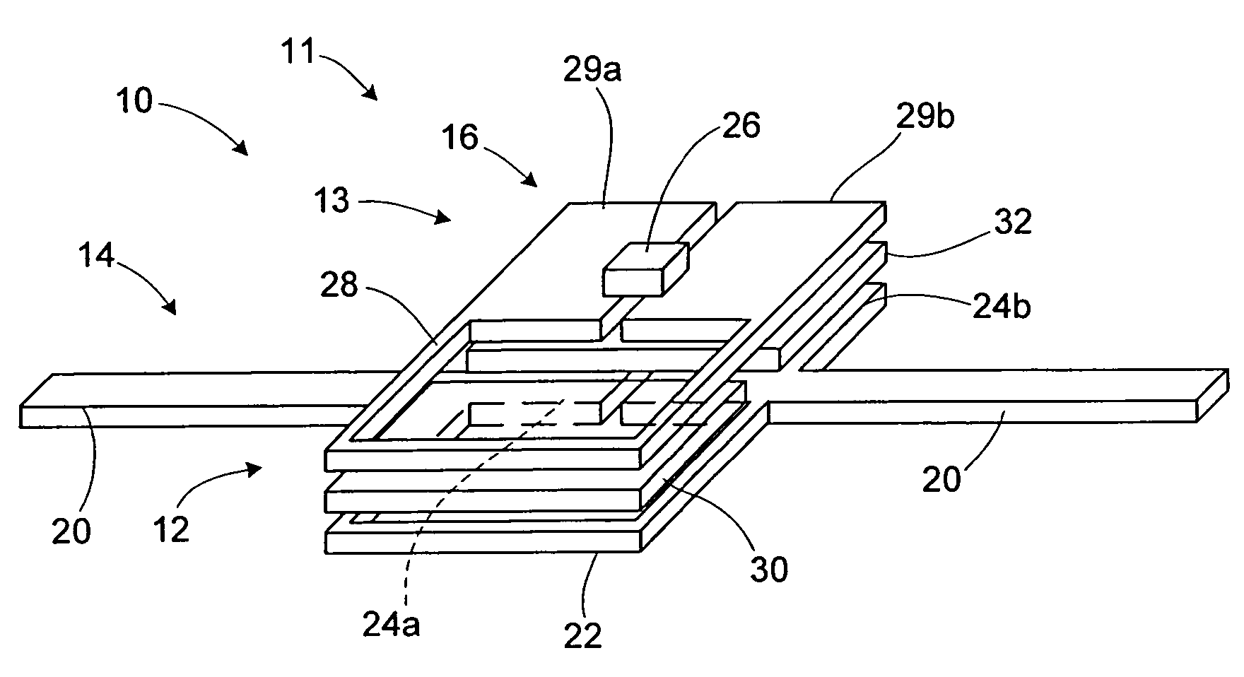
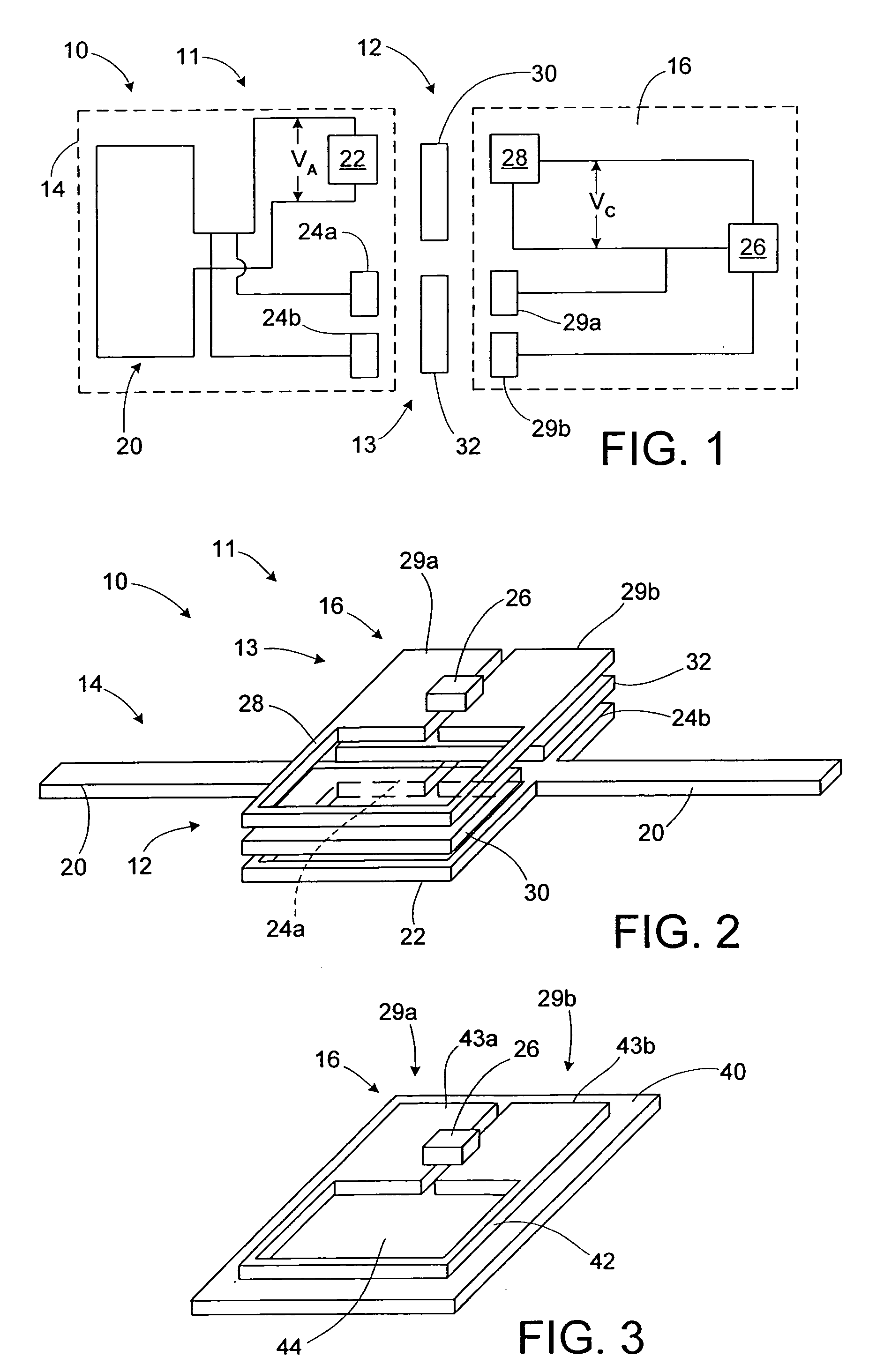
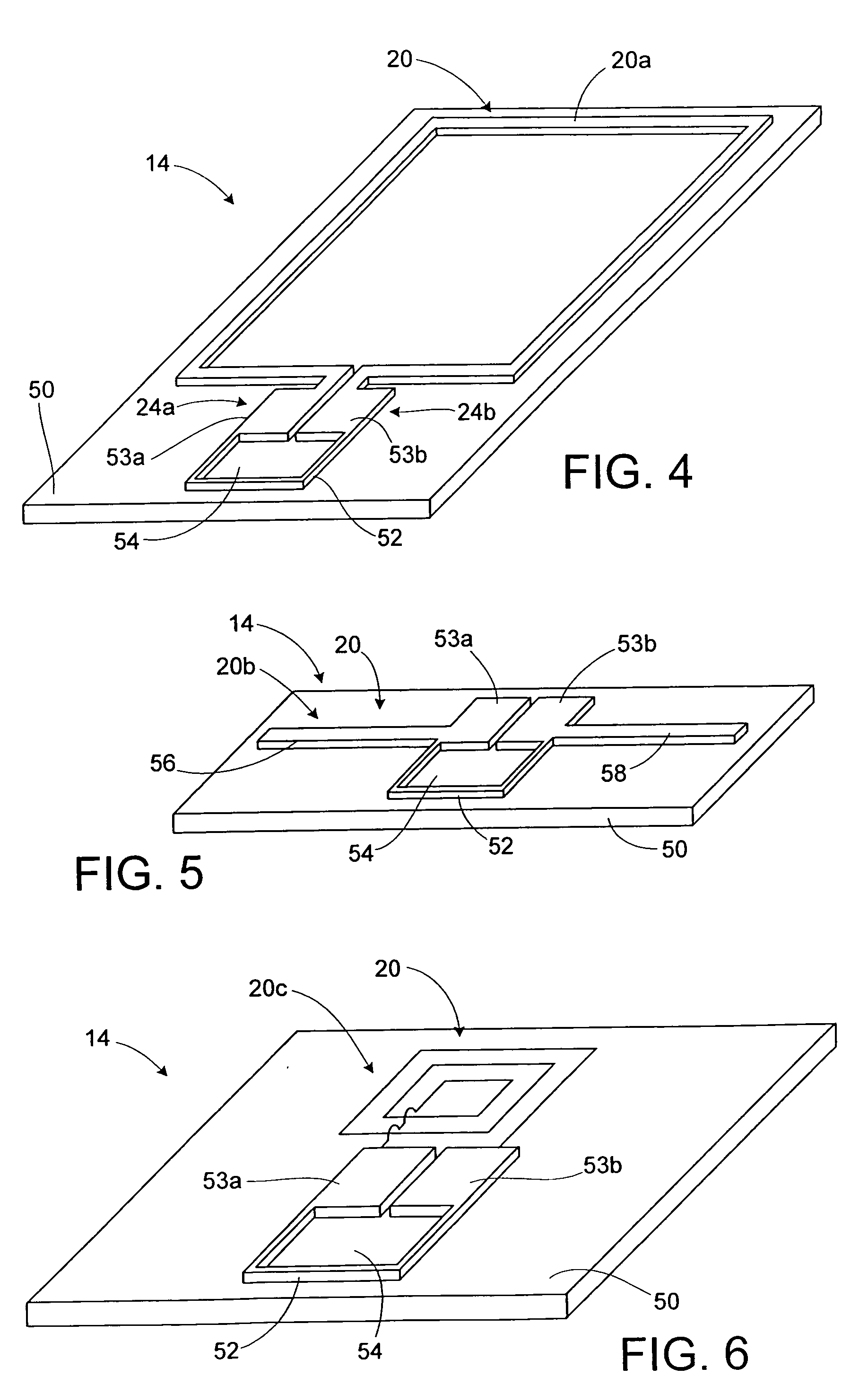
[0037] An RFID device, such as an RFID tag or label, includes both a magnetic coupler and a capacitive coupler coupling together operative portions of an interposer or strap, and an antenna. The interposer or strap includes a transponder chip, an interposer magnetic coupling element that is operatively coupled to the transponder, and one or more interposer capacitive coupling elements that are operatively coupled to the transponder. An antenna portion magnetic coupling element and a pair of antenna portion capacitive coupling elements are operatively coupled to the antenna. The magnetic coupling elements together constitute a magnetic coupler that is used to magnetically couple the transponder chip of the interposer to the RFID antenna. The interposer capacitive coupling elements are operatively coupled to the antenna portion capacitive coupling elements, thereby constituting a capacitive coupler. A high permeability material may be used to enhance the magnetic coupling between the ...


PUM


Abstract

An RFID device, such as an RFID tag or label, includes a combined reactive coupler electrically coupling a transponder chip to an antenna. The combined reactive coupler includes a magnetic coupler and a capacitive coupler. The magnetic coupler and the reactive coupler may have respective coupling elements on both the interposer and on an antenna substrate.

Description

BACKGROUND OF THE INVENTION [0001] 1. Field of the Invention [0002] This invention relates to the field of radio frequency identification (RFID) tags and labels. [0003] 2. Description of the Related Art [0004] RFID tags and labels have a combination of antennas and analog and / or digital electronics, which may include for example communications electronics, data memory, and control logic. RFID tags and labels are widely used to associate an object with an identification code. For example, RFID tags are used in conjunction with security-locks in cars, for access control to buildings, and for tracking inventory and parcels. Some examples of RFID tags and labels appear in U.S. Pat. Nos. 6,107,920, 6,206,292, and 6,262,292, all of which this application incorporates by reference. [0005] RFID tags and labels include active tags, which include a power source, and passive tags and labels, which do not. In the case of passive tags, in order to retrieve the information from the chip, a “base ...

Claims


Application Information

Patent Timeline
IPC IPC(8): G06K19/06G08B13/14
CPCG06K19/07749G06K19/07752G06K19/07756H01Q5/40H01Q1/2225H01Q7/00H01Q9/285G06K19/07786G06K19/077G06K19/07
Inventor FORSTER, IAN J.
Owner AVERY DENNISON CORP
Why Eureka
Try Eureka