Fuel injection valve

a technology of fuel injection valve and valve needle, which is applied in the direction of fuel injection apparatus, charge feed system, engine components, etc., can solve the problems of large leakage loss of hydraulic coupler, simple problems, and loss of lift at the valve needle, so as to reduce leakage loss, reduce leakage loss, and reduce the effect of load compensation

Inactive Publication Date: 2006-03-02
ROBERT BOSCH GMBH
View PDF6 Cites 14 Cited by
  • Summary
  • Abstract
  • Description
  • Claims
  • Application Information

AI Technical Summary

Benefits of technology

[0005] The fuel injector according to the present invention has the advantage that the hydraulic coupler already returns to its original position after a brief injection pause, the coupler gap refilling with hydraulic fluid in the process. The formation of a compensating chamber within the coupler filled at least partially with hydraulic fluid ensures an effective load compensation and a reliable filling of the coupler gap.
[0006] Providing a throttle opening between the compensating chamber and the coupler gap makes it possible to reduce leakage losses during the injection phase.
[0007] The use of an elastic diaphragm to delimit the compensating chamber has the advantage...

Problems solved by technology

This results in a lift loss at the valve needle.
Basic problems arise in certain operating states such as cold start, hot start, operation under emergency conditions, and at low system pressure.
This...

Method used


Image

  • Fuel injection valve
  • Fuel injection valve
  • Fuel injection valve

Examples


Embodiment Construction

[0014] In the following, exemplary embodiments of the present invention will be described by way of example. Identical parts have been provided with matching reference numerals in all of the figures.

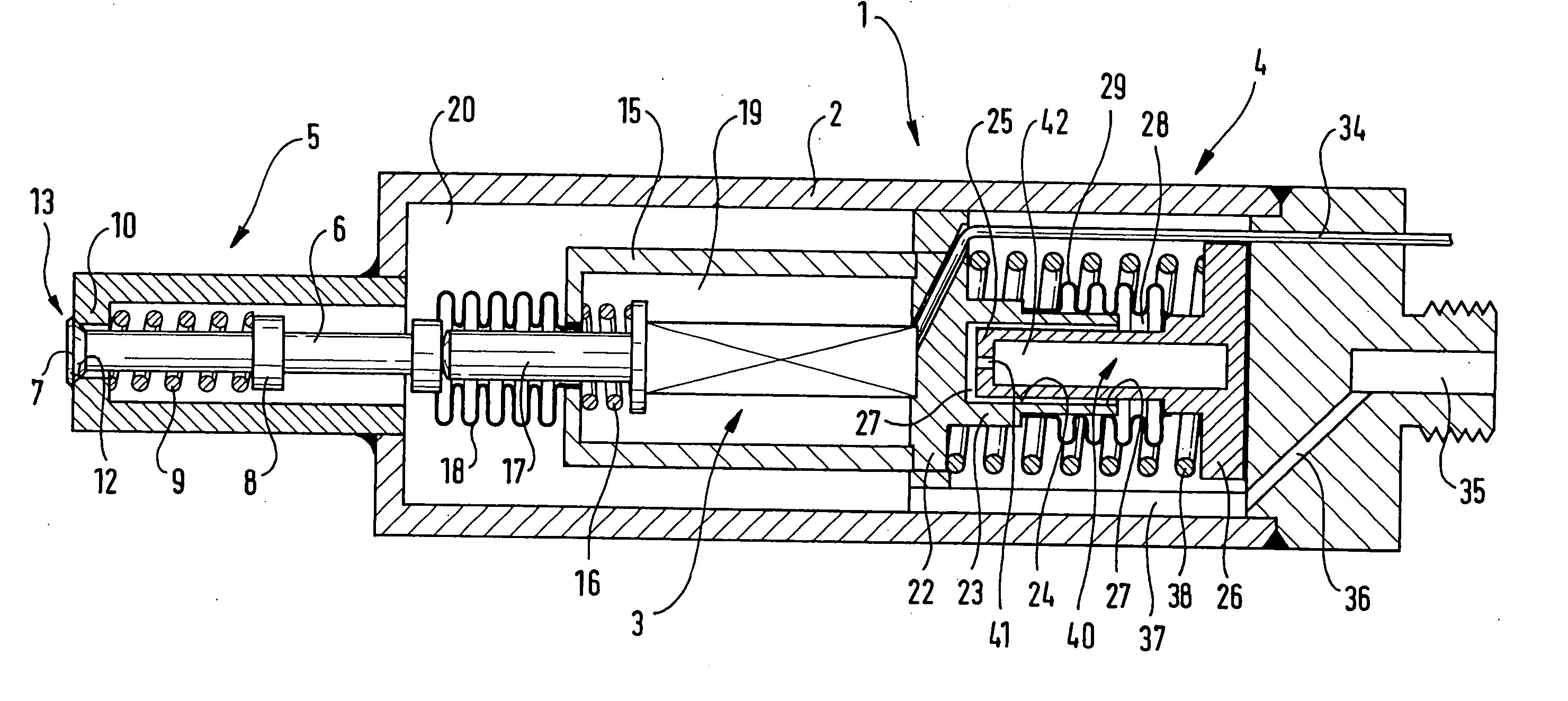
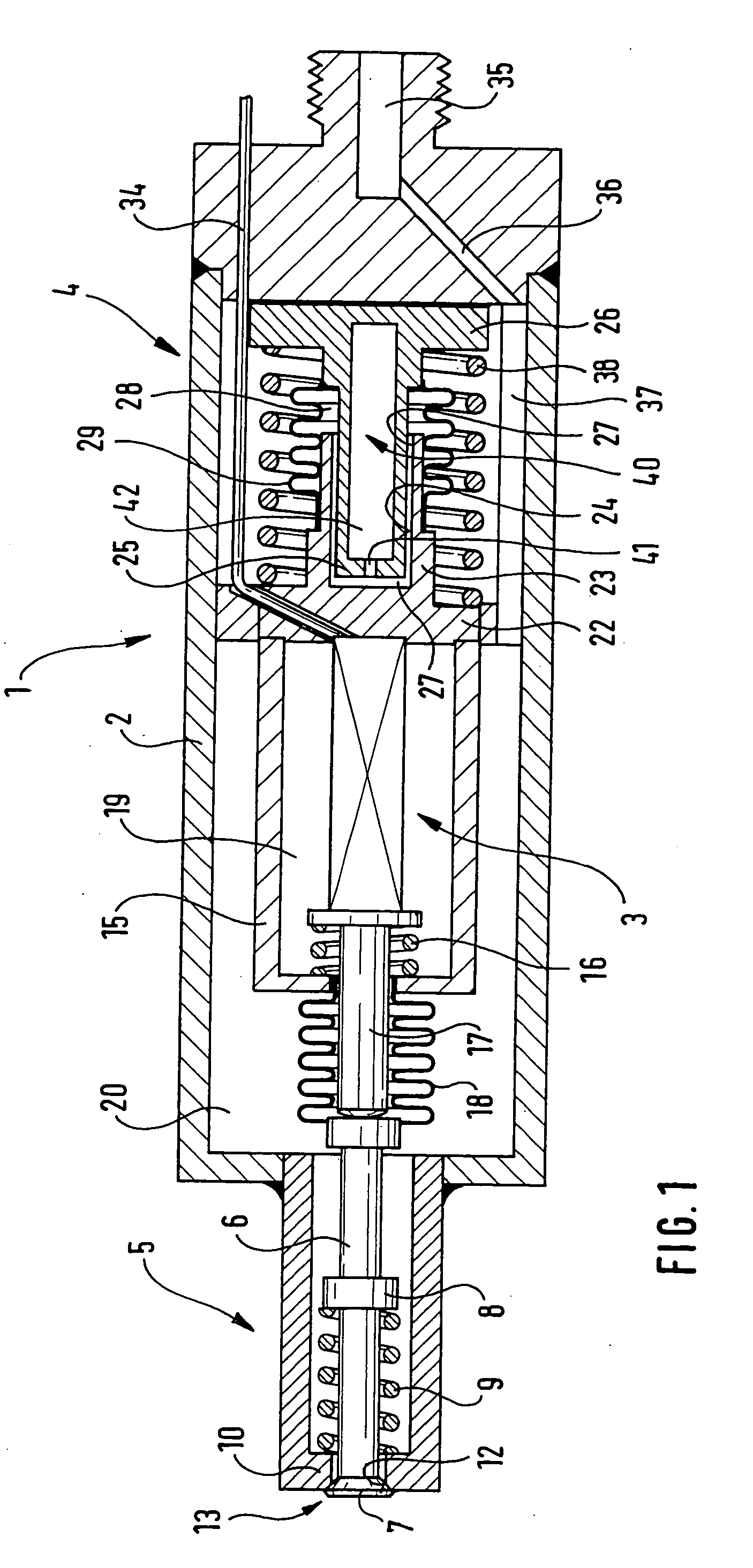
[0015] A fuel injector 1 according to the present invention shown in FIG. 1 in a longitudinal section is used in particular for the direct injection of fuel into a combustion chamber of a mixture-compressing internal combustion engine having external ignition. Arranged in a housing 2 in a mutually coaxial manner are a piezoelectric actuator 3, an hydraulic coupler 4 and a valve unit 5.

[0016] Valve unit 5 has a valve needle 6, which carries a valve-closure member 7 at its discharge-side end. Valve-closure member 7 together with a valve-seat surface 12 forms a sealing seat 13 of valve unit 5. Valve needle 6 has a flange 8 on which a valve spring 9 is braced. On the other side, valve spring 9 rests against an inwardly projecting collar 10 of housing 2 and axially pushes valve needle 6 in ...


PUM


Abstract

A fuel injector has a piezoelectric, electrostrictive or magnetostrictive actuator, a valve needle, which is in operative connection with the actuator and acted upon with a restoring force by a valve spring in a closing direction to actuate a valve-closure member; and an hydraulic coupler which encompasses a piston that at least partially engages in a receiving opening and forms a coupler gap therewith, which is filled with an hydraulic fluid; a cavity being formed in the piston, which is open toward the coupler gap and at least partially filled with the hydraulic fluid and forms a compensating chamber.

Description

BACKGROUND INFORMATION [0001] German Patent Application No. DE 35 33 085, for instance, describes a fuel injector having a piezoelectric actuator which is in operative connection with a valve needle and in doing so is braced via an hydraulic coupler. The hydraulic coupler includes a damping piston which engages in a blind hole in an upper valve portion. A gap formed between damping piston and blind hole is filled with hydraulic fluid. An annular diaphragm encloses a free end and forms a compensating chamber filled with hydraulic fluid. [0002] Due to mechanical, thermal and electrical loading, the piezoactuator is subject to linear variation. The linear variation of the piezoactuator caused by electrical triggering is selectively utilized to produce the valve lift. [0003] During the injection phase, the hydraulic coupler loses hydraulic fluid via the leakage gap between blind hole and damping piston. This results in a lift loss at the valve needle. During normal operation, the piezoa...

Claims


Application Information

Patent Timeline
IPC IPC(8): B05B1/08F02M51/06F02M61/08F02M61/16F02M63/00
CPCF02M51/0603F02M61/167F02M61/08
Inventor GERSCHWITZ, THOMASNOLLER, KLAUSYILDIRIM, FEVZI
Owner ROBERT BOSCH GMBH
Why Eureka
Try Eureka