Self-luminous planar display device and manufacturing method thereof

Inactive Publication Date: 2006-03-02
HITACHI DISPLAYS
View PDF0 Cites 2 Cited by
  • Summary
  • Abstract
  • Description
  • Claims
  • Application Information

AI Technical Summary

Benefits of technology

[0016] According to the means 1 of the present invention, the contact between the interlayer insulation film which insulates the first electrodes and the second electrodes and the adhesive agent which adheres the sealing frame to the back panel can be obviated and hence, the vacuum leakage attributed to a chemical reaction between the interlayer insulation film and the adhesive agent can be prevented whereby the vacuum leakage attributed to the contact can be prevented. Further, according to the means 2 of the present invention, contact portions of the interlayer insulation film which insulates the first electrodes and the second electrodes and the adhesive agent which adheres the sealing frame to the back panel are side surfaces of the interlayer insulation film which is present below the second electrodes (second electrode lead terminals) and hence, the chemical reaction betwee

Problems solved by technology

As a result of lowering of the hermetic property, the degree of vacuum of the inner space defined by the back panel, the

Method used


Image

  • Self-luminous planar display device and manufacturing method thereof
  • Self-luminous planar display device and manufacturing method thereof
  • Self-luminous planar display device and manufacturing method thereof

Examples


embodiment 1

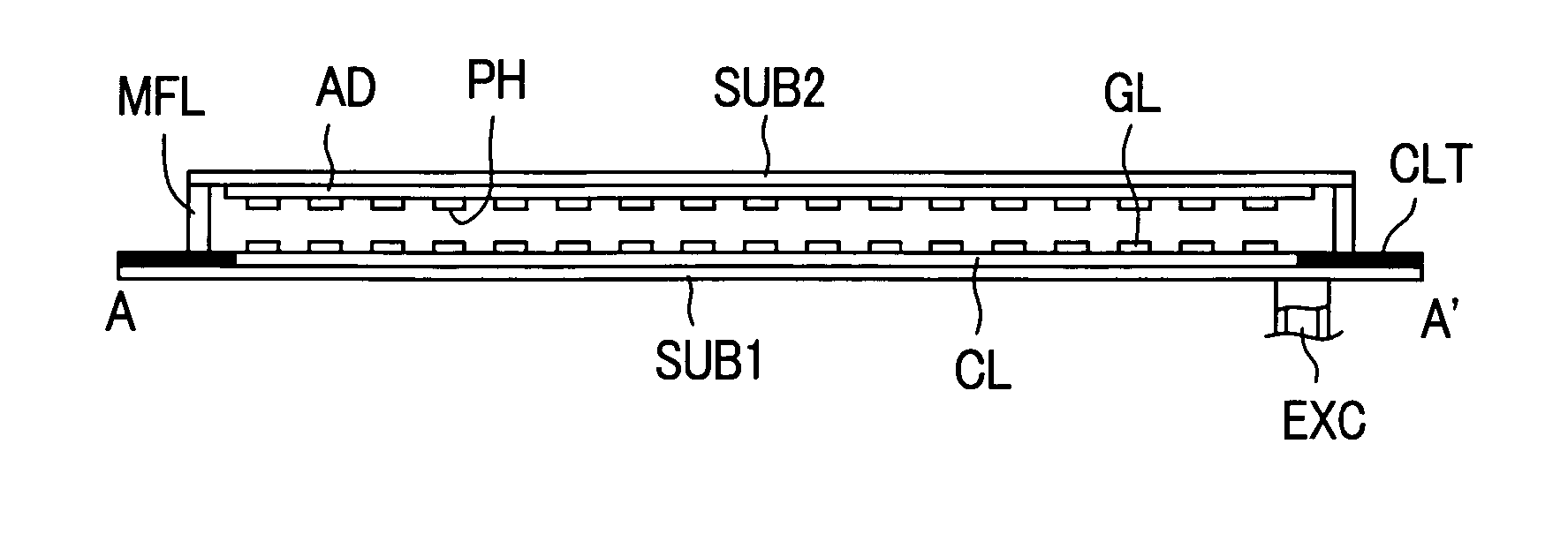
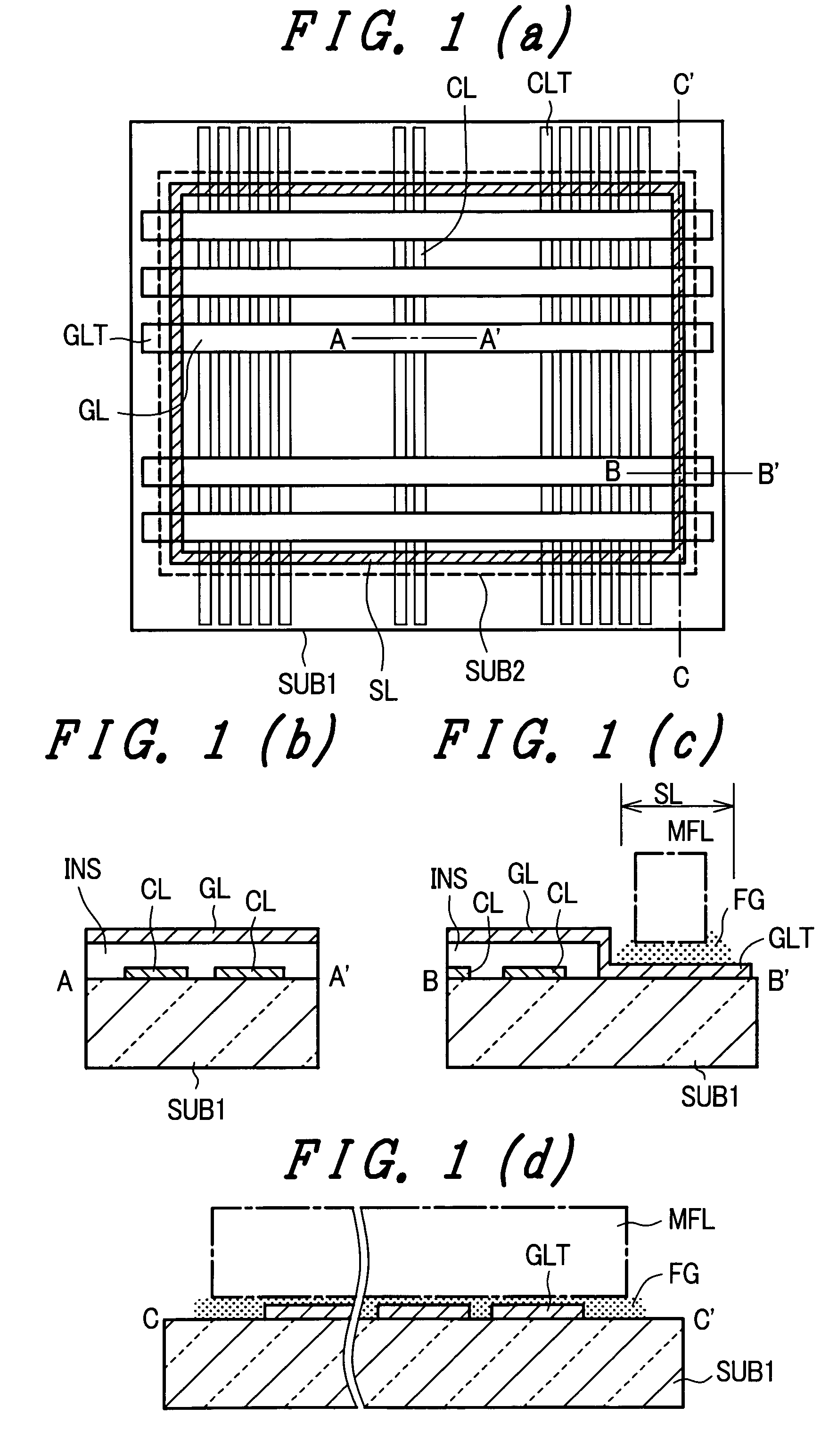
[0028]FIG. 1A, FIG. 1B, FIG. 1C and FIG. 1D are schematic views for explaining an embodiment 1 of a display panel constituting a self-luminous planar display device of the present invention, wherein FIG. 1A is a plan view for explaining the inner surface constitution of a back panel, FIG. 1B is a partial cross-sectional view taken along a line A-A′ in FIG. 1A, FIG. 1C is a partial cross-sectional view taken along a line B-B′ in FIG. 1A, and FIG. 1D is a partial cross-sectional view taken along a line C-C′ in FIG. 1A. Here, in a plan view of FIG. 1A, a position of a profile of a substrate (face substrate) SUB2 of a face panel is indicated by a broken line. The back panel and the face panel allow a sealing frame MFL to be interposed between inner brims of outer peripheries thereof. The back panel, the face panel and the sealing frame MFL are adhered to each other and are integrally formed using frit glass FG. A sealing region on the sealing frame MFL is indicated by symbol SL.

[0029] ...

embodiment 2

[0043]FIG. 3A, FIG. 3B and FIG. 3C are schematic views for explaining an embodiment 2 of a display panel constituting the self-luminous planar display device of the present invention, and also are views for explaining the inner surface constitution of a back panel. Here, a plan view of the back panel of the embodiment 2 is substantially equal to FIG. 1A. FIG. 3A is a partial cross sectional view taken along a line A-A′ in FIG. 1A, FIG. 3B is a partial cross-sectional view taken along a line B-B′ in FIG. 1A and FIG. 3C is a partial cross-sectional view taken along a line C-C′ in FIG. 1A. In the embodiment 2, the sealing frame MFL is interposed between inner brims of outer peripheries of the back panel and the face panel, and the sealing frame MFL is adhered to and integrally formed with the back panel and the face panel using frit glass FG as an adhesive agent. A sealing region in the sealing frame MFL is indicated by symbol SL.

[0044] In the same manner as the embodiment 1, on the b...

embodiment 3

[0055]FIG. 5 is a schematic view of an essential part for explaining an embodiment 3 of the display panel which constitutes the self-luminous planar display device of the present invention and also is a plan view of gate electrode lead terminals and a portion of a sealing frame of a back panel. The embodiment 3 adopts the structure of the embodiment 2 as the basic constitution thereof, wherein the gate electrode lead terminal GLT in a sealing region SL is formed in an elongated planar shape in which a length of one side periphery of the gate electrode lead terminal GLT is set longer than a lead distance of the gate electrode lead terminal GLT in the sealing region. An interlayer insulation film which is interposed below the gate electrode lead terminal GLT is present having a planar shape which follows a planar shape of the gate electrode lead terminal GLT.

[0056] In FIG. 5, projections P are formed over side peripheries of the second electrode lead terminal GLT in the sealing regio...


PUM


Abstract

The present invention suppresses the generation of deterioration of degree of vacuum attributed to a chemical reaction between an insulation film and an adhesive agent for adhering a sealing frame. An insulation film formed between first electrodes and first electrode lead terminals and second electrodes and second electrode lead terminals on a back panel is formed except for a sealing region where the back panel and a face panel are sealed. In a second electrode lead terminal side of the sealing region, only an adhesive-agent layer which adheres the back panel and the sealing frame and the second electrode lead terminals are present between a sealing frame and a back substrate.

Description

BACKGROUND OF THE INVENTION [0001] 1. Field of the Invention [0002] The present invention relates to a display device which makes use of the emission of electrons into a vacuum, and more preferably to a self-luminous planar display device which includes a display panel formed by sealing a back panel having electron sources for emitting electrons and a face panel having phosphor layers of a plurality of colors which emit lights when excited by electrons taken out from the back panel and electron accelerating electrodes using a sealing frame and a manufacturing method thereof. [0003] 2. Description of the Related Art [0004] A color cathode ray tube has been popularly used conventionally as an excellent display device which exhibits high brightness and high definition. However, along with the realization of high image quality of recent information processing device and television broadcasting, there has been a strong demand for a planar display device which is light-weighted and requir...

Claims


Application Information

Patent Timeline
IPC IPC(8): H01J63/04H01J1/62
CPCH01J9/261H01J31/123H01J29/90H01J9/32
Inventor KIJIMA, YUUICHIKANEKO, YOSHIYUKIFUJIMURA, TAKASHI
Owner HITACHI DISPLAYS
Why Eureka
Try Eureka