
Harmonic wireless transponder sensor and method

a wireless transponder and wireless sensor technology, applied in the field of sensors, can solve the problems of invasive insulation integrity, end the useful life of pipes, vessels or structural parts, and high cost of inspection

Active Publication Date: 2006-03-02
MICHIGAN STATE UNIV +1
View PDF16 Cites 5 Cited by
  • Summary
  • Abstract
  • Description
  • Claims
  • Application Information

AI Technical Summary

Benefits of technology

[0005] The instant invention provides, for example, a non-invasive remote wireless means to detect a condition that may lead to inadvertent latent corrosion of an insulated steel pipe, vessel or structural member. In its broad scope, the instant invention provides a method for detecting a latent environmental effect or a latent structural change at a known remote location. The method of the instant invention comprises three steps. The first step is to use a harmonic electromagnetic transponder at the known remote concealed location of the latent environmental effect or the latent structural change, the harmonic electromagnetic transponder having a reactive portion which reacts to the latent environmental effect or latent structural change to modify the harmonic emission of the transponder. The second step is to remotely interrogate the transponder by directing electromagnetic radiation at the transponder. The third step is to use the harmonic emission of the transponder to remotely determine the latent environmental effect or latent structural change. When the latent environmental effect is, for example, moisture that may lead to corrosion of an insulated carbon steel pipe, vessel or structural member, then the reactive portion of the transponder can be an electrical conductor, such as steel wire, that corrodes when exposed to moisture.

Problems solved by technology

Inadvertent latent corrosion of such pipes, vessels or structural members can occur under the insulation which corrosion can be expensive to repair and can even end the useful life of the pipe, vessel or structural member.
Such inspections are expensive and invasive of the integrity of the insulation.

Method used


Image

  • Harmonic wireless transponder sensor and method
  • Harmonic wireless transponder sensor and method
  • Harmonic wireless transponder sensor and method

Examples


example 1

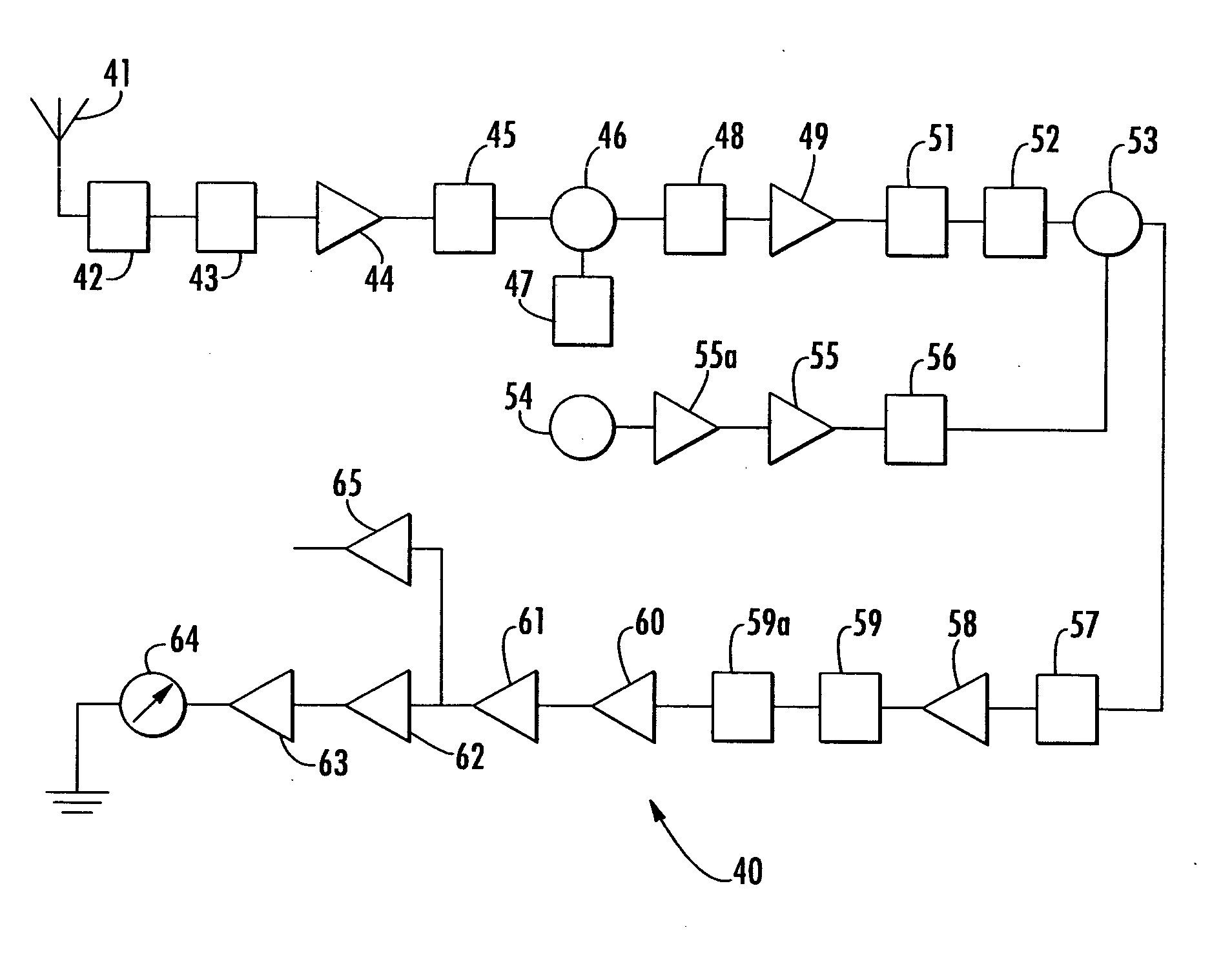
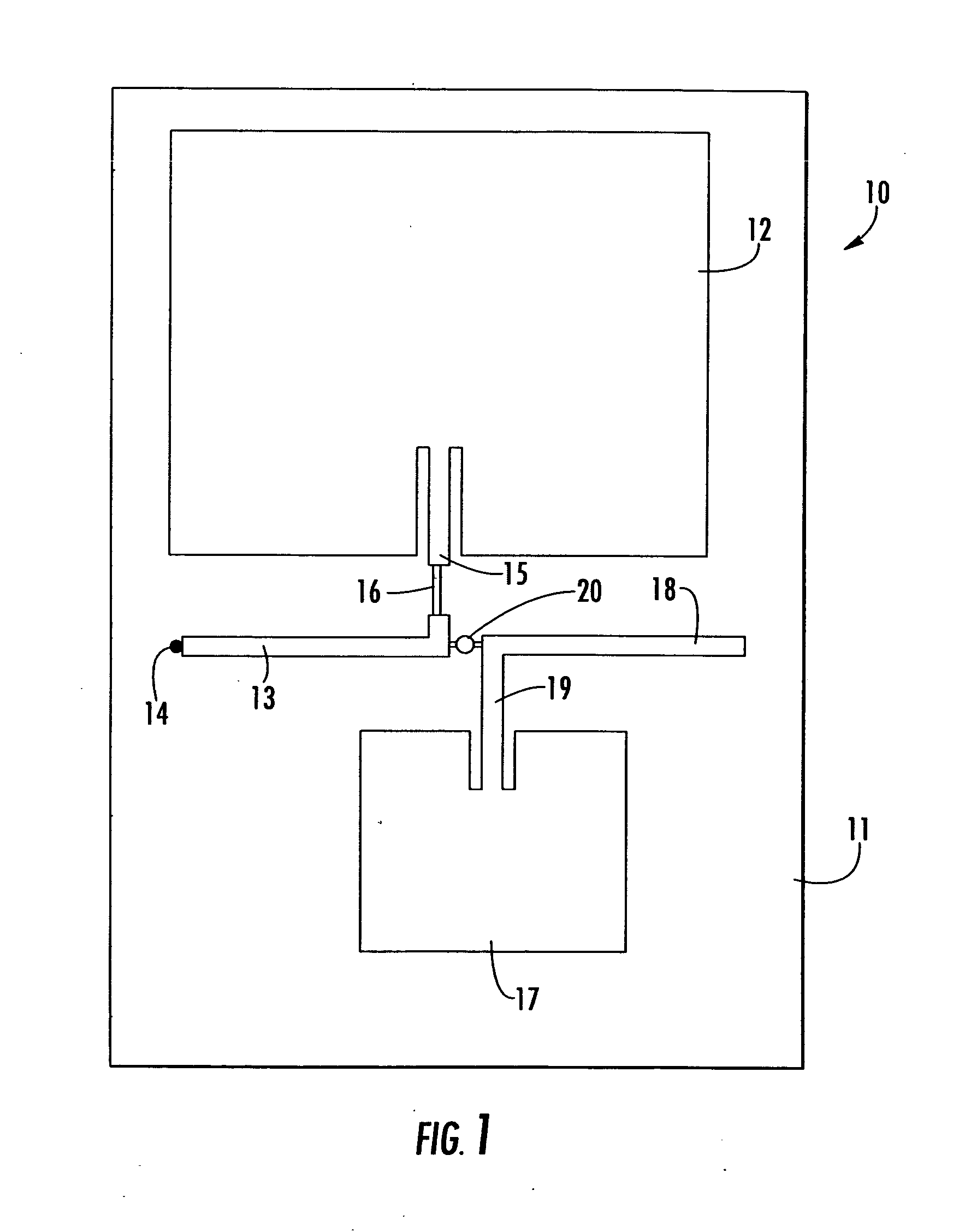
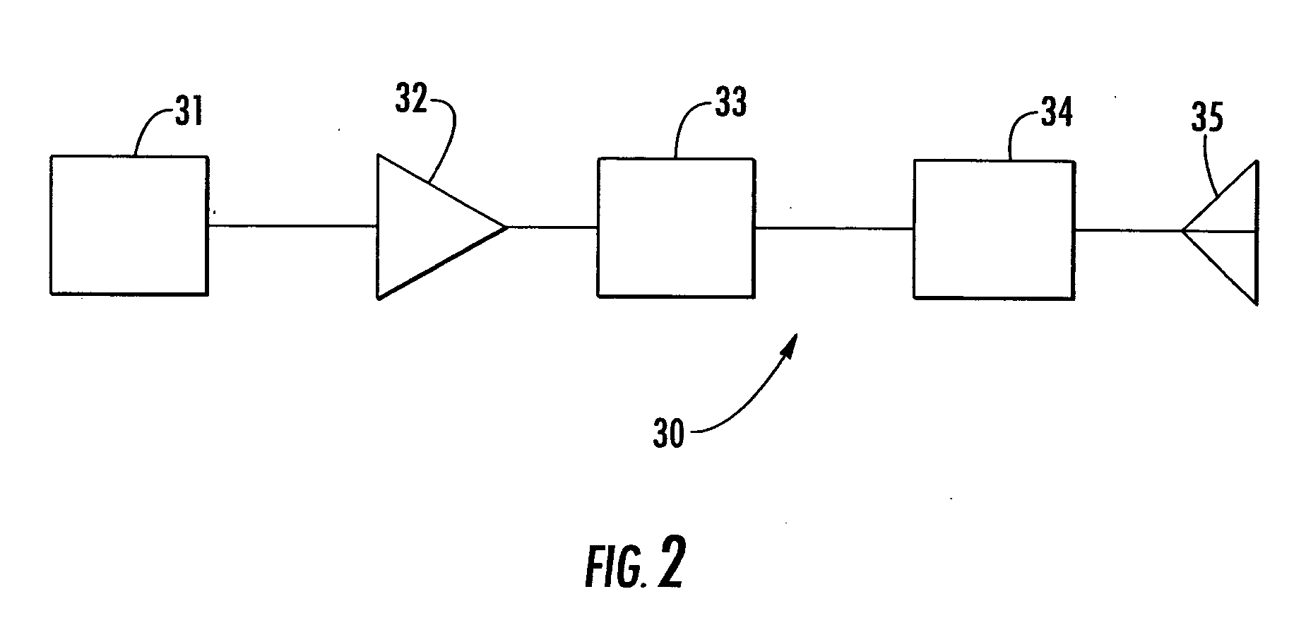
[0018] The transponder 10 of FIG. 1 is positioned under the thermal insulation of a carbon steel vessel located in a tank farm of an industrial facility. The antennas 35 and 41 of the transmitter 30 and the receiver 40 of FIGS. 2 and 3 respectively are pointed at the tank from a distance of fifty feet. The transmitter 30 is turned on to direct electromagnetic radiation at the transponder 10. The signal indicated by the meter 64 of the receiver 40 is twelve decibels.

[0019] Every month for the next sixty nine months, the antennas 35 and 41 of the transmitter 30 and the receiver 40 of FIGS. 2 and 3 respectively are pointed at the tank from a distance of fifty feet. The transmitter 30 is turned on to direct electromagnetic radiation at the transponder 10. The signal indicated by the meter 64 of the receiver 40 is twelve decibels each time the transponder 10 is interrogated. However, the interrogation at seventy months indicates a response of only two decibels.

[0020] The insulation is ...

example 2

[0021] A transponder like the transponder 10 of FIG. 1 (but not having the carbon steel wire 16 in the transmission line 15 and instead having a carbon steel wire soldered at each end thereof to and bridging the first resonator 13 and the second resonator 18) is positioned under the thermal insulation of a carbon steel tank located in a tank farm of an industrial facility. The antennas 35 and 41 of the transmitter 30 and the receiver 40 of FIGS. 2 and 3 respectively are pointed at the tank from a distance of sixty feet. The transmitter 30 is turned on to direct electromagnetic radiation at the transponder 10. The signal indicated by the meter 64 of the receiver 40 is two decibels.

[0022] Every month for the next eighty eight months, the antennas 35 and 41 of the transmitter 30 and the receiver 40 of FIGS. 2 and 3 respectively are pointed at the tank from a distance of fifty feet. The transmitter 30 is turned on to direct electromagnetic radiation at the transponder 10. The signal in...

example 3

[0024] A reference transponder like the transponder 10 of FIG. 1 is produced but having no carbon steel wire in the first transmission line 15. The reference transponder is positioned under the thermal insulation near one end of a carbon steel tank of an over-the-road tank trailer. A transponder like the transponder 10 of FIG. 1 is produced (but having no carbon steel wire in the first transmission line 15 but having a thermostatic switch bridging the first resonator 13 and the second resonator 18) and positioned under the thermal insulation of the tank trailer near the other end of the tank trailer. The tank trailer is used to transport molten sulfur from a sulfur recovery installation to a sulfuric acid production plant. The molten sulfur in the tank trailer needs to be at least one hundred and forty degrees Celsius when the tank trailer leaves the sulfur recovery installation so that the sulfur is still molten by the time the tank trailer arrives at the sulfuric acid plant. The t...


PUM


Abstract

A method for detecting a latent environmental effect (such as a corrosive environment under insulation) or a latent structural change (such as a crack in a concealed structural member) at a known remote concealed location. The method of the instant invention includes three steps. The first step is to use a harmonic electromagnetic transponder at the known remote concealed location of the latent environmental effect or the latent structural change, the harmonic electromagnetic transponder having a reactive portion which reacts to the latent environmental effect or latent structural change to modify the harmonic emission of the transponder. The second step is to remotely interrogate the transponder by directing electromagnetic radiation at the transponder. The third step is to use the harmonic emission of the transponder to remotely determine the latent environmental effect or the latent structural change.

Description

BACKGROUND [0001] The instant invention is in the field of sensors and more specifically the instant invention is in the field of wireless sensors employing harmonic electromagnetic transponders. [0002] A harmonic electromagnetic transponder receives electromagnetic radiation at a fundamental frequency and emits electromagnetic radiation at a harmonic of the fundamental frequency. The harmonic of the fundamental frequency is usually the first harmonic (or twice the fundamental frequency). A passive harmonic electromagnetic transponder requires no power source (other than the power of the incoming electromagnetic radiation) for its operation. An active harmonic electromagnetic transponder requires a power source for its operation. As discussed by Maas, The RF and Microwave Circuit Design Cookbook, 1998, Chapter 2, a common passive harmonic electromagnetic transponder comprises a receiving antenna tuned to resonate at the frequency of the incoming electromagnetic radiation, an emittin...

Claims


Application Information

Patent Timeline
Patent Type & Authority Applications(United States)
IPC IPC(8): G01S13/76
CPCH04Q9/00G06K19/07749
Inventor MILLER, THEODORE E. JR.LIENING, EUGENE L.WARREN, MALCOLM W. IIKEMPEL, LEO C.CHARVAT, GREGORY L.
Owner MICHIGAN STATE UNIV
Learn More