Signal driving method and apparatus for a light emitting display

Active Publication Date: 2006-03-02
SAMSUNG DISPLAY CO LTD
View PDF13 Cites 41 Cited by
  • Summary
  • Abstract
  • Description
  • Claims
  • Application Information

AI Technical Summary

Benefits of technology

[0014] Accordingly, the present invention provides a light emitting display having a plurality of OLEDs commonly coupled to a pixel driver

Problems solved by technology

Many wires are required to drive a pixel 10, causing difficulty in arranging the wir

Method used


Image

  • Signal driving method and apparatus for a light emitting display
  • Signal driving method and apparatus for a light emitting display
  • Signal driving method and apparatus for a light emitting display

Examples


Embodiment Construction

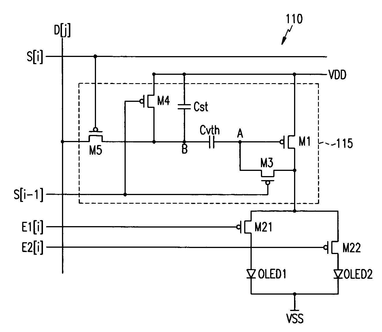
[0052] Throughout the specification, the terminology “present scan line” refers to a scan line which is going to transmit a present selection signal, and “previous scan line” refers to a scan line that has transmitted a selection signal before transmission of the present selection signal. Further, a pixel that emits light in accordance with the selection signal of the present scan line will be referred to as a “present pixel”, and a pixel that emits light in accordance with the selection signal of the previous scan line will be referred to as a “previous pixel.”

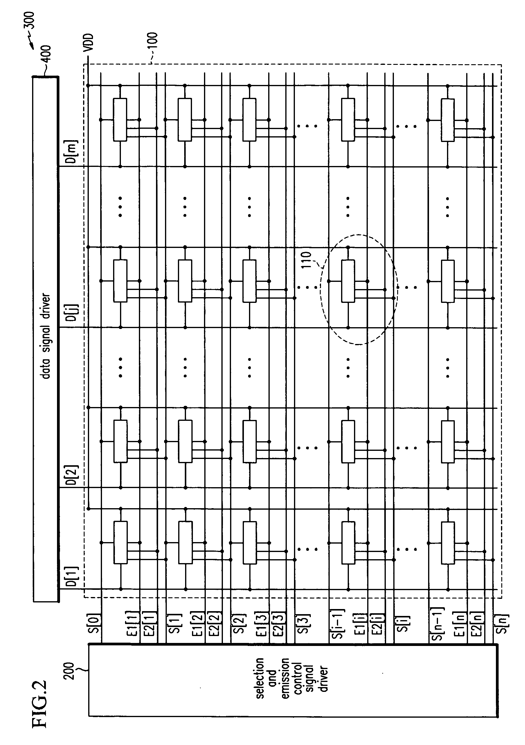
[0053]FIG. 2 shows a configuration of an organic light emitting display 300 according to embodiments of the present invention. The organic light emitting display 300 includes a display panel 100, a selection and emission control signal driver 200, and a data signal driver 400. The display panel 100 includes a plurality of selection scan lines S[i] arranged in rows, a plurality of emission control lines E1[i], E2[i] also arran...


PUM


Abstract

A light emitting display having a display area including data lines, selection scan lines, first and second emission control lines, and pixels; a selection signal generator sequentially outputting selection signals having a selection pulse; and an emission control signal generator generating a first control signal, the first control signal sequentially outputting a first emission control signal having an emission control pulse and a shifted first emission control pulse while shifting the first emission control signal by the first length of time, and sequentially outputting a second emission control signal having the emission control pulse and a shifted second emission control pulse while shifting the second emission control signal by the first length of time.

Description

CROSS REFERENCE TO RELATED APPLICATION [0001] This application claims priority to and the benefit of Korean Patent Application No. 10-2004-0068550 filed on Aug. 30, 2004 in the Korean Intellectual Property Office, the entire content of which is incorporated herein by reference. BACKGROUND OF THE INVENTION [0002] 1. Field of the Invention [0003] The present invention relates to a light emitting display, and more particularly to a light emitting display using electroluminescence of organic materials. [0004] 2. Description of the Related Art [0005] In general, an organic light emitting diode display electrically excites phosphorus organic components and generates an image by voltage-programming or current-programming an n×m matrix of organic light emitting cells. These organic light emitting cells have features similar to a diode and are called organic light emitting diodes (OLEDs). [0006] The OLED includes an anode, an organic thin film, and a cathode layer. The organic thin film laye...

Claims


Application Information

Patent Timeline
IPC IPC(8): G09G3/30H05B44/00
CPCG09G3/3233G09G2300/0465G09G2300/0861G09G2300/0819G09G2300/0852G09G2300/0804G09G3/30
Inventor EOM, KI-MYEONG
Owner SAMSUNG DISPLAY CO LTD
Why Eureka
Try Eureka