Software defined radio system

a radio system and software technology, applied in the direction of synchronisation signal speed/phase control, amplitude demodulation, multiple modulation transmitter/receiver arrangement, etc., can solve the problems of increasing the number of components and the size of the substrate, cooling devices, and not being suitable for small wireless devices. , to achieve the effect of reducing the number of components, facilitating the design of rf circuits, and reducing costs

Inactive Publication Date: 2006-03-02
HITACHI LTD
View PDF2 Cites 23 Cited by
  • Summary
  • Abstract
  • Description
  • Claims
  • Application Information

AI Technical Summary

Benefits of technology

[0013] The present invention includes an anti-aliasing filter having a cutoff frequency fc that is fixed or common to respective communication protocols, an AD converter and a DA converter each having a clock signal input that can vary a sampling frequency, and a PLL circuit that can vary the frequency of the clock signal, performs the sampling by setting the sampling frequency not lower than the integral multiple of the signal bandwidth and double the cutoff frequency, and makes it possible to communicate the signals of the communication protocols having plural and different bandwidths in multiple modes.
[0014] The present invention exhibits an effect of reducing the number of components and lowering the cost, because the anti-aliasing filter with a fixed cutoff frequency, the DA converter, and the AD converter can be used commonly while communicating the signals of the plural communication protocols having different bandwidths in multiple modes. And if the sampling frequencies are set almost equally, the bandwidths of respective components in the RF unit 30 can be made common, which leads to facilitating the RF circuit design, reducing the number of components, and lowering the cost.

Problems solved by technology

And the filter using a superconducting material can vary the cutoff frequency, but it requires a cooling device, which is not suitable for a small wireless device.
It is also conceivable to prepare plural filters and select one, which leads to increasing the number of components and the size of the substrate and increasing the cost.
However, these methods involve quality deterioration of the signal.

Method used


Image

  • Software defined radio system
  • Software defined radio system
  • Software defined radio system

Examples


Embodiment Construction

[0027] The preferred embodiments relating to the present invention will be described with reference to the accompanying drawings.

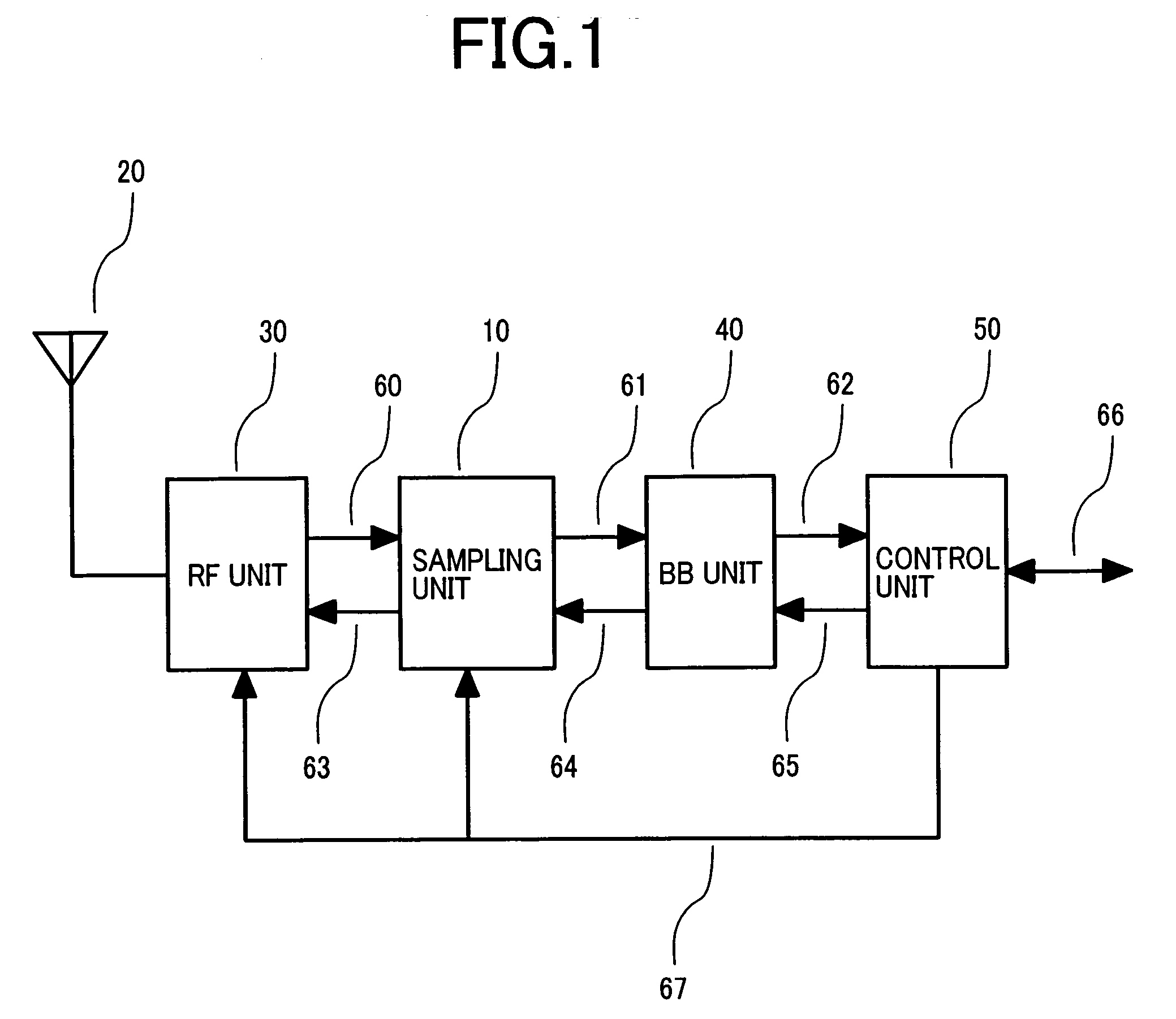
[0028]FIG. 1 illustrates a block diagram of the software defined radio system that adopts a sampling device relating to the invention. The example here is the software defined radio system capable of the multimode communications having the sampling in the base band assumed. The software defined radio system includes a sampling unit 10, an antenna 20, an RF unit 30, a BB unit 40, and a control unit 50.

[0029] A received signal by the antenna 20, conforming to a specific communication protocol, is inputted to the RF unit 30. The RF unit 30 includes a duplexer, an LNA (Low Noise Amplifier), a band pass filter, a mixer, an IQ demodulator, a HPA (High Power Amplifier), and an AGC (Auto Gain Control) and so forth. The received signal by the antenna 20 is subjected to the following processing by the RF unit 30: TX / RX separation, bandwidth restriction, low-noise ...


PUM


Abstract

The invention provides a technique that saves rate conversion accompanying complicated calculations and shares an analog filter for anti-aliasing in a sampling device. The sampling device employs an anti-alias filter having a fixed cutoff frequency, an A/D converter and a D/A converter each having a clock signal input, which are capable of varying a sampling frequency, and a PLL circuit capable of varying the frequency of a clock signal; and it sets the sampling frequency not lower than an integral multiple of a signal bandwidth and double the cutoff frequency for sampling.

Description

CLAIM OF PRIORITY [0001] The present application claims priority from Japanese application JP 2004-243090 filed on Aug. 24, 2004, the content of which is hereby incorporated by reference into this application. FIELD OF THE INVENTION [0002] The present invention relates to a software defined radio system that transmits / receives signals of plural and different communication protocols, which is suitable in use especially for a case that the plural communication protocols have different signal bandwidth. BACKGROUND OF THE INVENTION [0003] Many radio systems have been made with different communication protocols. In such circumstances, there is a radio system that varies the system function by varying the software program and reconfiguring the hardware to implement the radio system function with plural systems on the common platform, which is generally called the software defined radio system. Many efforts toward the software defined radio system have been introduced with various treatise...

Claims


Application Information

Patent Timeline
Patent Type & Authority Applications(United States)
IPC IPC(8): H04L27/06
CPCH04L27/0008H04L7/04
Inventor ISHII, HIROTAKETSUNEHARA, KATSUHIKOYANO, TAKASHI
Owner HITACHI LTD
Why Eureka
Try Eureka