
Power consumption controlling apparatus for high frequency amplifier

a technology of power consumption control and amplifier, which is applied in the direction of high frequency amplifier, low noise amplifier, substation equipment, etc., can solve the problems of power consumption, power consumption, and the inability to improve signal quality, so as to achieve the effect of reducing the power consumption of the power amplifier

Inactive Publication Date: 2006-03-02
SHARP KK +1
View PDF6 Cites 88 Cited by
  • Summary
  • Abstract
  • Description
  • Claims
  • Application Information

AI Technical Summary

Benefits of technology

[0012] An object of the present invention is to provide a power consumption controlling apparatus which can optimally adjust parameters such as a power supply voltage to minimize power consumption of a power amplifier while satisfying desired target characteristics (especially, signal: quality).
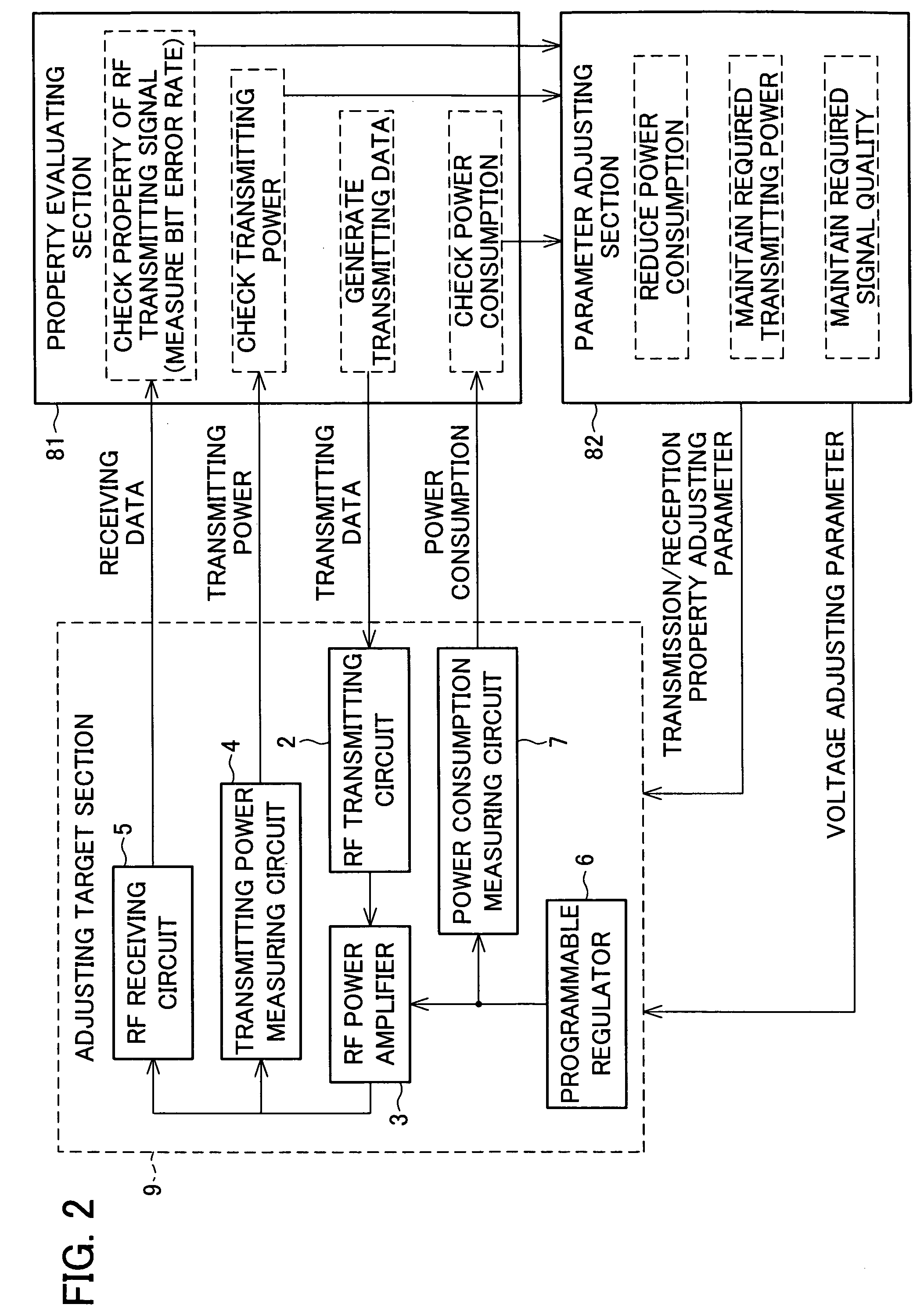
[0014] According to, the above arrangement, the evaluating section evaluates whether or not the receiving signal obtained from the receiving circuit satisfies a predetermined quality. Thus, by evaluating the quality of the receiving signal, the quality of the transmitting signal is evaluated. Then, the power supply voltage and the bias voltage are adjusted by the adjusting section to reduce the power consumption of the high frequency amplifier in a range in which the receiving signal satisfies a predetermined quality, that is, in a range in which the high frequency transmitting signal satisfies a predetermined quality. With this, it becomes possible to reduce the power consumption of the high frequency amplifier while maintaining the required quality of the high frequency transmitting signal.

Problems solved by technology

That is, the power consumption of the power amplifier 52 accounts for a large part of the power consumption of the RF analog circuit.
However, the conventional technology does not refer to a quantitative adjustment range which indicates to what extent the power supply voltage and the bias voltage can be adjusted without deteriorating a signal quality.
Therefore, even in the case in which signal distortion occurs when the power supply voltage of the power amplifier 102 is reduced, the deterioration in signal quality cannot be improved.

Method used


Image

  • Power consumption controlling apparatus for high frequency amplifier
  • Power consumption controlling apparatus for high frequency amplifier
  • Power consumption controlling apparatus for high frequency amplifier

Examples


Embodiment Construction

[0026] The following explains one embodiment of the present invention in reference to FIGS. 1 to 7.

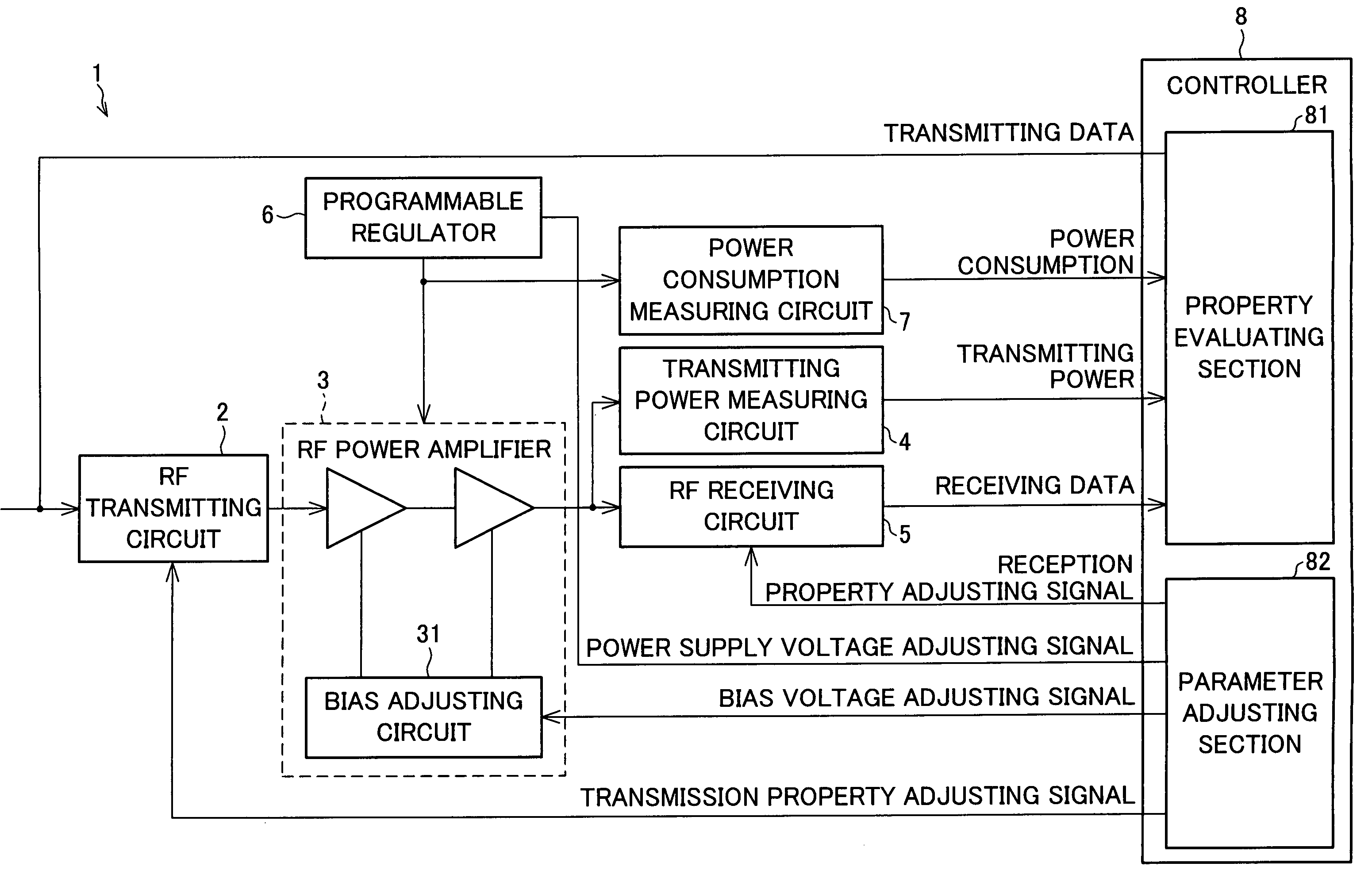
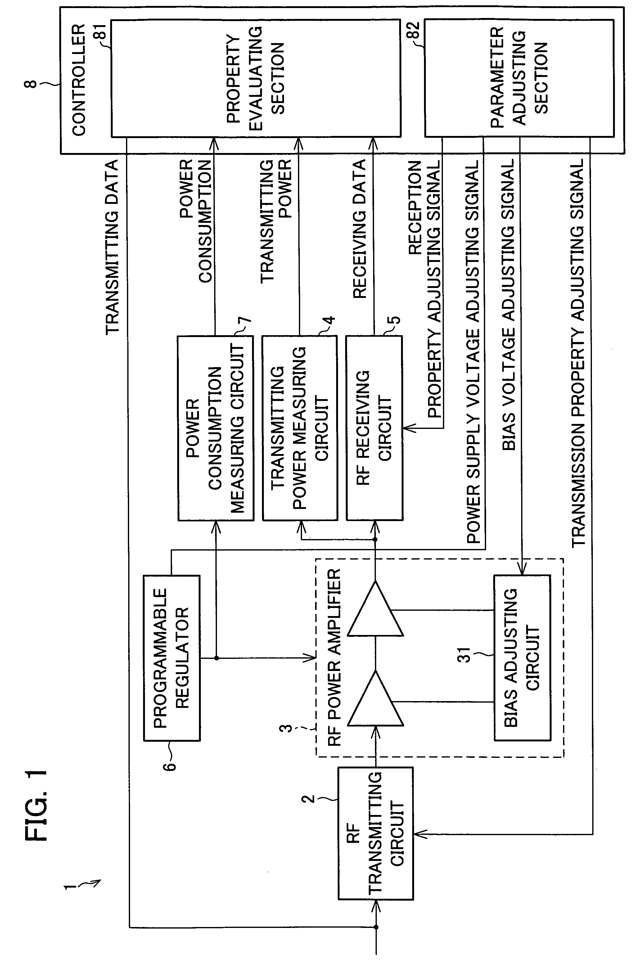
[0027]FIG. 1 shows an arrangement of substantial parts of a transmitting system 1 of the present embodiment. FIG. 2 shows an adjusting system of the transmitting system 1. The transmitting system 1 is applied to, for example, an IEEE802.11b wireless LAN system having a plurality of power sources.

[0028] As shown in FIG. 1, the transmitting system 1 includes an RF transmitting circuit 2, an RF power amplifier 3, a transmitting power measuring circuit 4, an RF receiving circuit 5, a programmable regulator 6, a power consumption measuring circuit 7, and a controller 8.

[0029] The RF transmitting circuit 2 is a circuit which converts an inputted baseband transmitting data into an analog IF signal and then upconverts the IF signal to generate a transmitting signal of transmission frequency.

[0030] The RF power amplifier 3 is an amplifier which amplifies the transmitting signal supplied fro...


PUM


Abstract

A power consumption controlling apparatus controls power consumption of a high frequency amplifier to reduce the power consumption by adjusting a power supply voltage and a bias voltage of the high frequency amplifier which amplifies a high frequency transmitting signal. The power consumption controlling apparatus includes: a receiving circuit for receiving the high frequency transmitting signal amplified by the high frequency amplifier; an evaluating section for evaluating whether or not a receiving signal obtained from the receiving circuit satisfies a predetermined quality; and an adjusting section for adjusting the power supply voltage and the bias voltage in a range in which the receiving signal evaluated by the evaluating section satisfies the predetermined quality.

Description

[0001] This Nonprovisional application claims priority under 35 U.S.C. § 119(a) on Patent Application No. 2004 / 253533 filed in Japan on Aug. 31, 2004, the entire contents of which are hereby incorporated by reference. FIELD OF THE INVENTION [0002] The present invention relates to an apparatus for controlling power consumption to reduce the power consumption of a high frequency amplifier included in a system, such as a mobile phone or a wireless LAN. BACKGROUND OF THE INVENTION [0003] As mobile information devices become more prevalent, there is an increasing demand for a longer continuous operable time and a longer charging battery life of those devices. Especially, there is a strong demand for reducing the power consumption of an RF (Radio Frequency) analog circuit which is the basis of a wireless system. [0004]FIG. 8 shows an arrangement of the RF analog circuit in a general wireless system. FIG. 9 shows a result obtained by measuring a distribution of the power consumption in the...

Claims


Application Information

Patent Timeline
IPC IPC(8): H01Q11/12H04B1/16H04B1/38
CPCH03F1/0205H03F1/0211H03F1/0261H04B2001/045H03F2200/294H03F2200/372H03F2200/465H03F3/189H03F1/02H03F3/24
Inventor URATANI, MUNEHIROKASAI, YUJIHIGUCHI, TETSUYATAKAHASHI, EIICHI
Owner SHARP KK
Learn More