Method of temperature sensing

a temperature sensing and temperature variable technology, applied in the direction of program control, testing/monitoring control system, instruments, etc., can solve the problems of not providing additional signal processing of temperature variables, fieldbuses are limited to the delivery of relatively low electrical power, and fieldbus transmitters are often more than twice as expensive as traditional transmitters

Active Publication Date: 2006-03-02
WATLOW ELECTRIC MFG
View PDF54 Cites 67 Cited by
  • Summary
  • Abstract
  • Description
  • Claims
  • Application Information

AI Technical Summary

Benefits of technology

[0017] Various embodiments of the present invention provide an improved distributed operations system for monitoring, controlling, diagnosing or acquiring data from field devices that operate over a bitbus and interface to a fieldbus.

Problems solved by technology

Transmitter based systems are also wired to the I / O device, but the I / O device accommodates only standardized voltage or current inputs and does not provide additional signal processing of the temperature variable.
Fieldbuses are also limited to the delivery of relatively low levels of electrical power to assure that the fieldbus-based transmitters satisfy electrical power requirements of intrinsically safe or increased safety electrical industry standards required for safe operation in process environments where explosive gases may be present.
Fieldbus transmitters are often more than twice as expensive as traditional transmitters, due in part to the more sophisticated electronics required to process more parameters and to the complexity of the communications signal processing for a fieldbus.
Many operational or process systems do not require the full capabilities of the fieldbus and do not justify the high implementation cost, especially when monitoring simple, less-costly sensors, actuation devices, and discrete devices such as contact closures, switches, and / or digital on-off devices.
Generally, current bitbus-based devices do not include extensive diagnostic capabilities, do not provide signal conditioning that is often required in a harsh operating environment, and do not interface well with higher level operational systems.
Due to the limited bandwidth of the bitbus, current bitbus systems do not include digital diagnostics information processing of diagnostic parameters that are contained in the digital bitbus message from a sensor or actuating device.

Method used


Image

  • Method of temperature sensing
  • Method of temperature sensing
  • Method of temperature sensing

Examples


Embodiment Construction

[0034] The following description is merely exemplary in nature and is not intended to limit the invention, its applications, or uses.

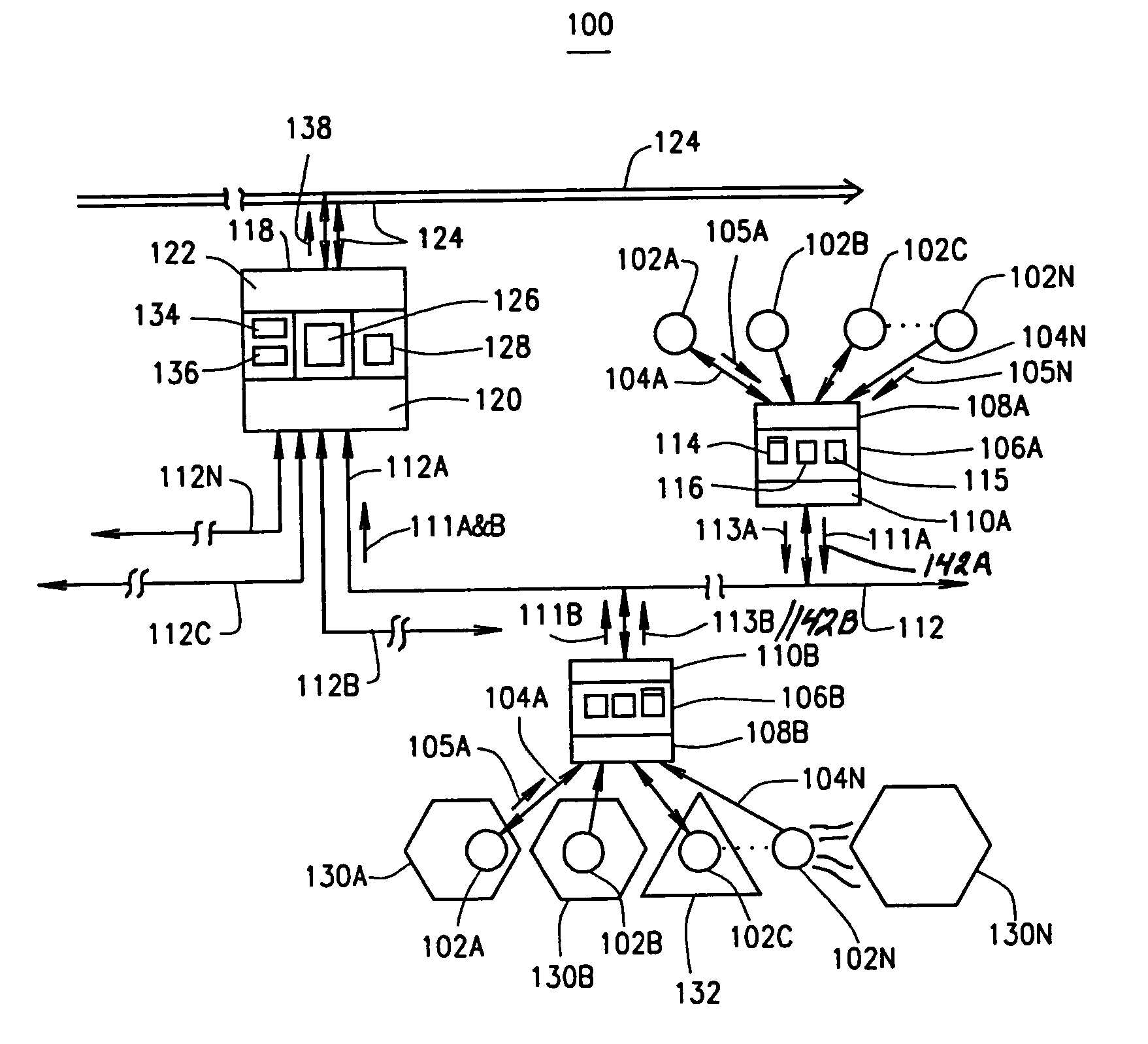
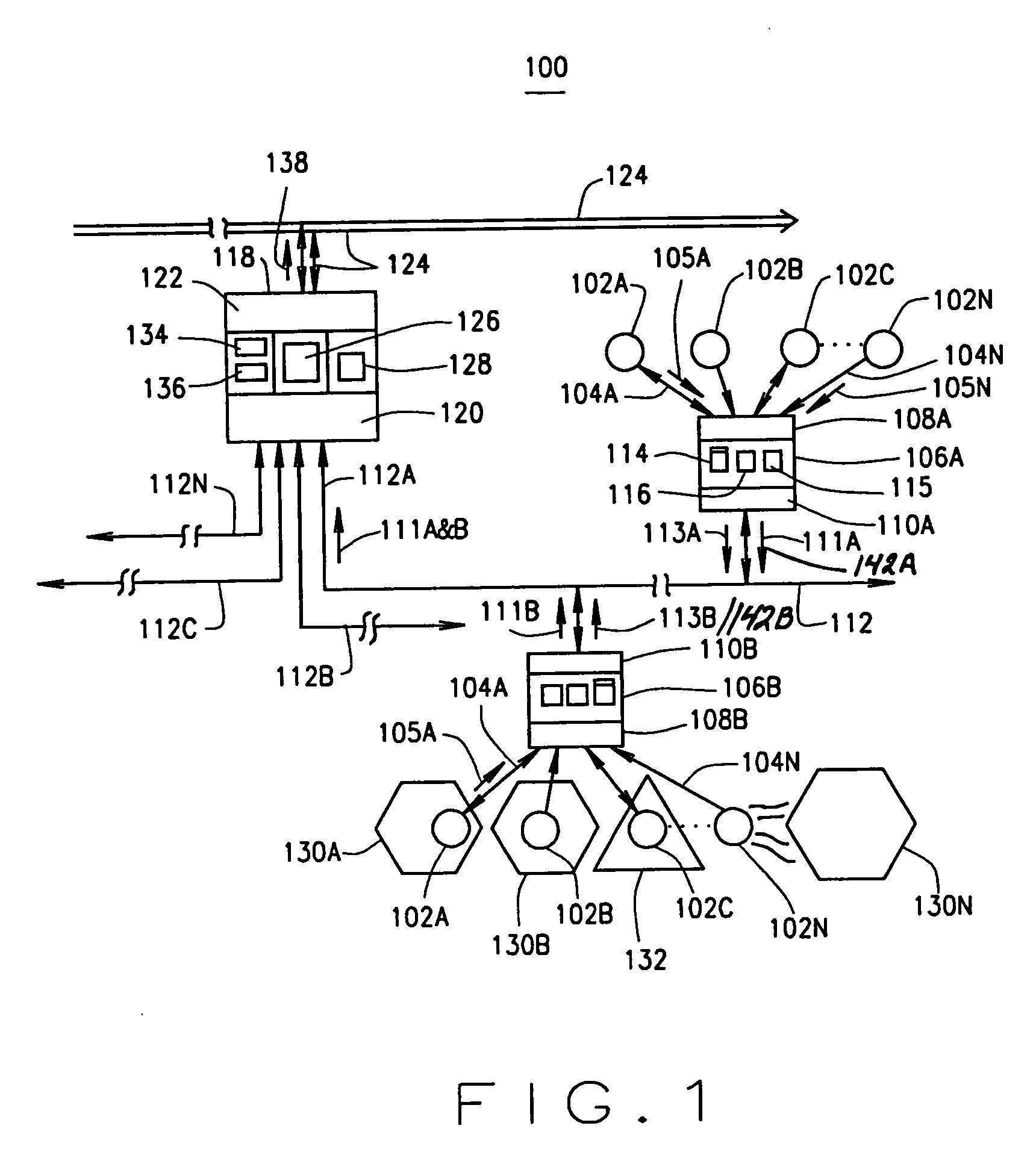
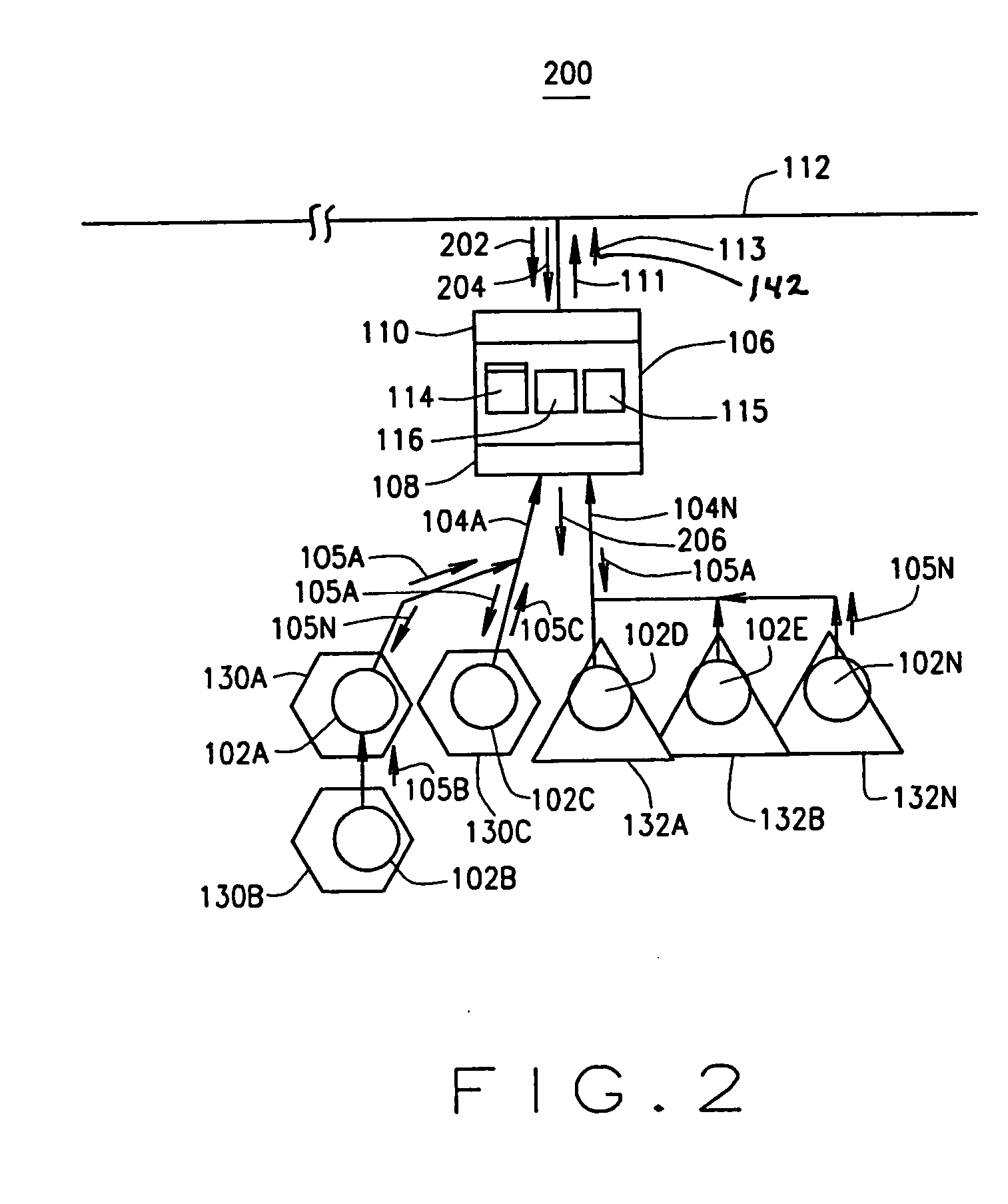
[0035] In one embodiment, a distributed operations system with integrated diagnostics includes a field device for generating a field operating characteristic. The system also includes a field processing module coupled to the field device for receiving the field operating characteristic from the field device. The field processing module includes a field diagnostic component and a field communication component and is configured for generating field operating data including a field diagnostic parameter as a function of the field operating characteristic. The system also includes a bitbus for communication with the field processing module and for receiving the field operating data from the field processing module. The system further includes an auxiliary processing module for communicating with the bitbus and for receiving the field operating data. The au...


PUM


Abstract

A method of diagnosing a temperature sensing system having a temperature sensor, a field processing module coupled to the temperature sensor, a bitbus, a fieldbus, and an auxiliary processing module communicating with the bitbus and the fieldbus. The method includes generating a temperature characteristic at the temperature sensor, processing the temperature characteristic at the field processing module, and generating field operating data including a temperature diagnostic parameter as a function of the temperature characteristic. The method also includes communicating the field operating data including the temperature diagnostic parameter over the bitbus from the field processing module to the auxiliary processing module, generating at the auxiliary processing module auxiliary field data as a function of the received field operating data, and communicating the auxiliary field data over the fieldbus.

Description

CROSS-REFERENCE TO RELATED APPLICATIONS [0001] This application claims the benefit of U.S. Provisional Application No. 60 / 605,819, filed on Aug. 31, 2004. This application is also related to U.S. patent application Ser. No. ______, (Attorney Docket 7377-000070 / US01), filed Aug. 31, 2005, entitled DISTRIBUTED DIAGNOSTICS OPERATIONS SYSTEM; U.S. patent application Ser. No. ______, (Attorney Docket 7377-000070 / US02), filed Aug. 31, 2005, entitled TEMPERATURE SENSING SYSTEM; and U.S. patent application Ser. No. ______, (Attorney Docket 7377-000070 / US03), filed Aug. 31, 2005, entitled METHOD OF DIAGNOSING AN OPERATIONS SYSTEM; and PCT patent application Ser. No. ______, (Attorney Docket 7377-000070 / WO / POA), filed Aug. 31, 2005, entitled OPERATIONS SYSTEM DISTRIBUTED DIAGNOSTIC SYSTEM. The disclosures of the above applications are incorporated herein by reference.FIELD OF THE INVENTION [0002] The present invention relates to a method for a distributed operational system and, more specific...

Claims


Application Information

Patent Timeline
Patent Type & Authority Applications(United States)
IPC IPC(8): G06F15/00G01M99/00
CPCG01K1/024G01K1/026G01K1/028G05B2219/31211G01K15/00G05B23/0254G01K3/14
Inventor LENZ, GARY A.SCHUH, WILLIAM C.CULBERTSON, DAVID P.FENNEWALD, KENNETH F.STEINHAUSER, LOUIS P.MCNUTT, LEON J.
Owner WATLOW ELECTRIC MFG
Why Eureka
Try Eureka