
Method and measurement probe for the performance of measurements in water supply systems

a technology for water supply systems and measurement probes, applied in the direction of measurement devices, structural/machine measurement, instruments, etc., can solve the problems of leakage loss, large case size, and only rarely detected leakage losses, and achieve easy application and good gripping facilities

Inactive Publication Date: 2006-03-09
MARTINEK PETER
View PDF21 Cites 12 Cited by
  • Summary
  • Abstract
  • Description
  • Claims
  • Application Information

AI Technical Summary

Benefits of technology

The invention provides a method for detecting leaks in water supply systems using measurement probes that can detect flow, pressure, and flow noise. These probes are installed at regular intervals or continuously along the water pipe network, allowing for the analysis of the flow rate and direction. The method can be performed using a single measurement probe or multiple probes. The invention also includes the use of a noise detector and a noise correlator to accurately locate the leak. The method can be carried out using a reader unit or terminals connected to a data collector. The invention helps to minimize water loss and costs associated with leak detection and analysis.

Problems solved by technology

Losses, in some cases considerable, occur due to pipe ruptures or also due to leaky sections in the area of the water pipes or in the area of the water consumers.
Since the pipes of the water supply networks are as a rule laid underground, leakage losses can only rarely be detected immediately, and especially not if the individual leakage losses are not excessively large.
Such leakage losses are in particular those quantities of water resulting from the difference between the quantity of water supplied and the quantity of water to be charged to consumers.
With such equipment and the method provided here, the first steps may well be able to be taken towards a leakage loss that is to be located within a large area, but a specific search for a leak and a precise fault location is not possible by this means.
It must also be regarded as a drawback that the retrofitting of a water supply system with such equipment would probably be a failure on cost grounds alone, not only for the setting up, but also for the day-to-day business.

Method used


Image

  • Method and measurement probe for the performance of measurements in water supply systems
  • Method and measurement probe for the performance of measurements in water supply systems
  • Method and measurement probe for the performance of measurements in water supply systems

Examples


Embodiment Construction

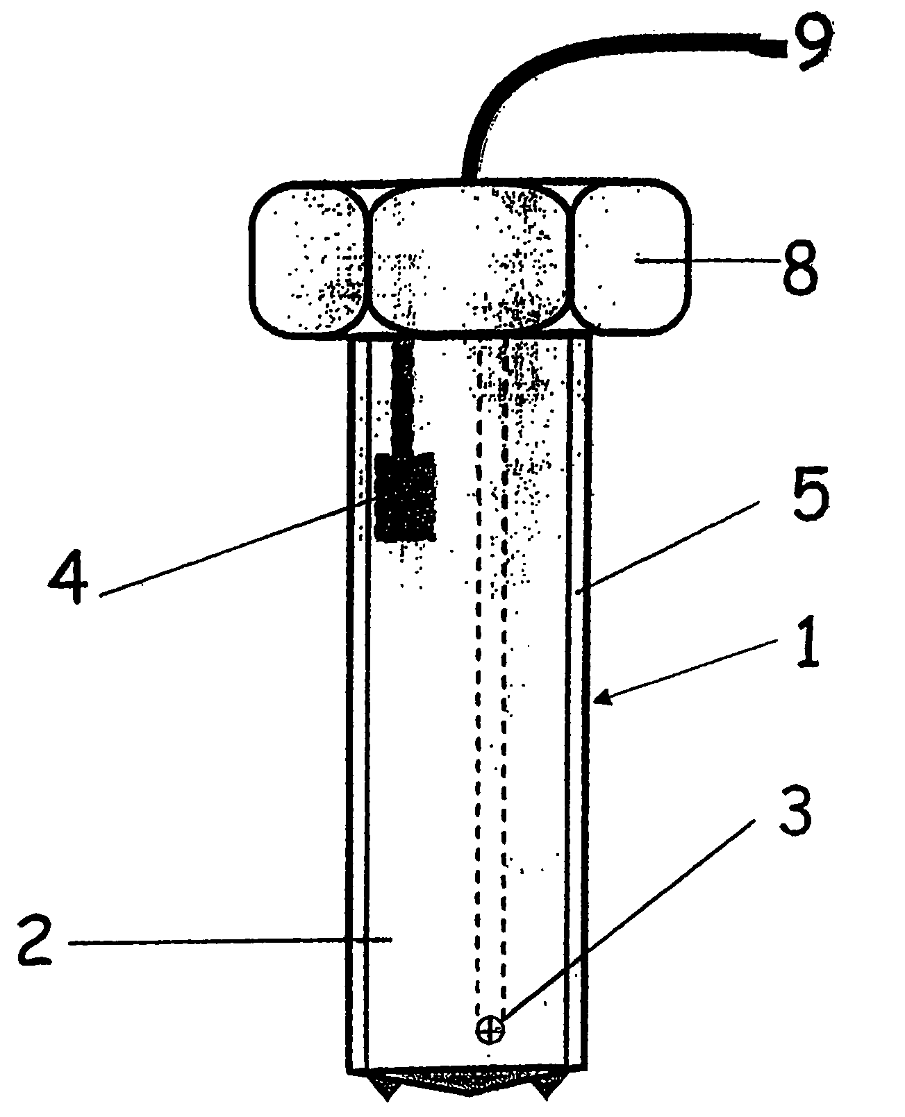
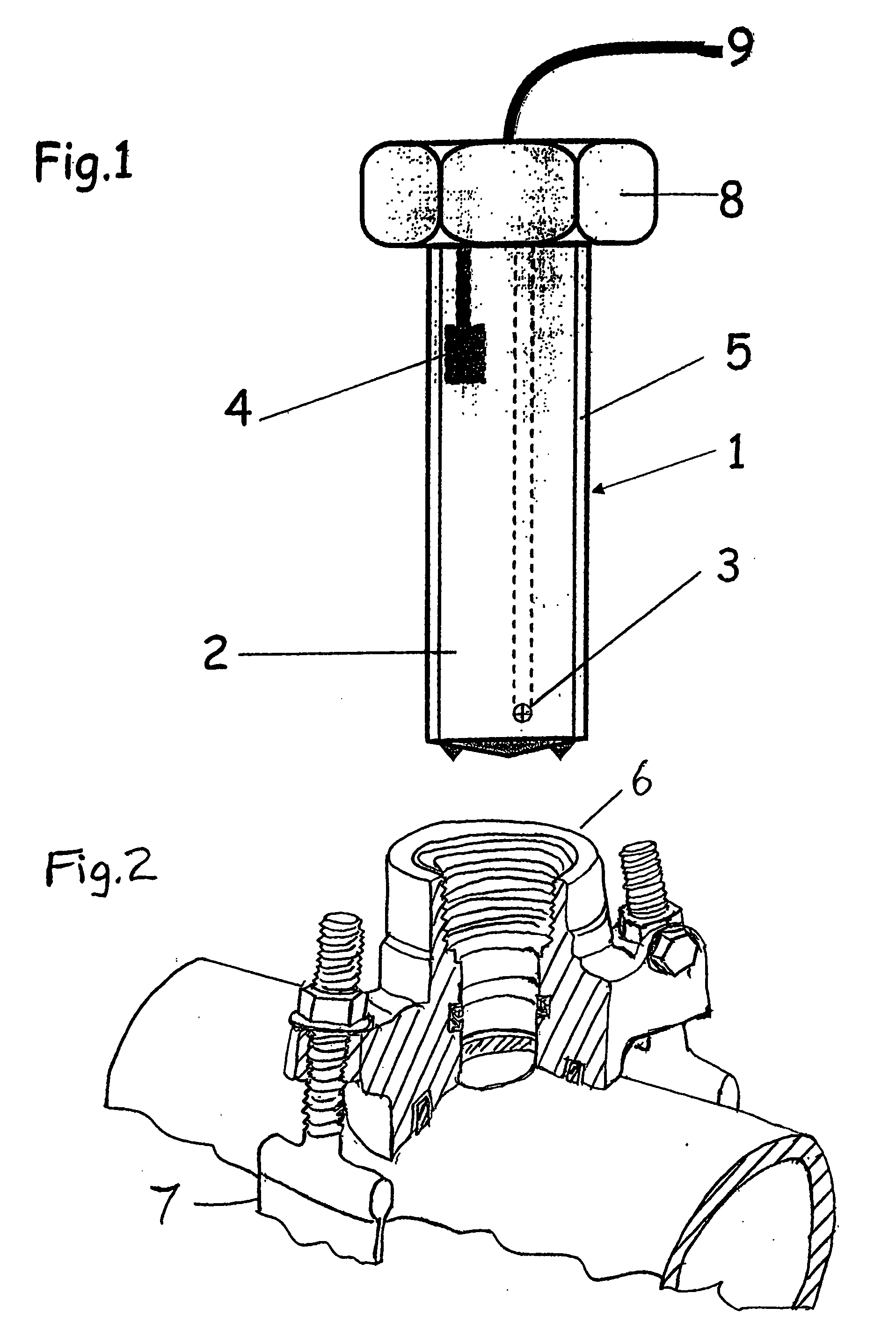
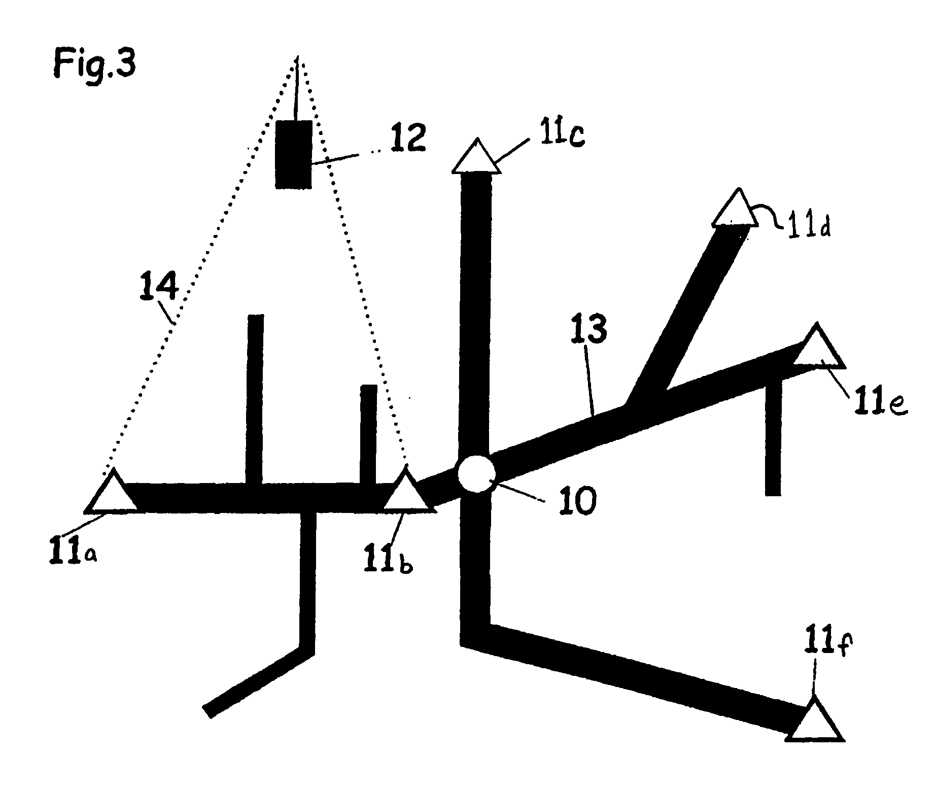
[0024] Measuring elements, i.e. a probe 2 for the flow measurement, a pressure sensor 3 and a noise detector 4, for the output of measured quantities in respect of the flow, namely the flow rate and direction, the water pressure and the flow noise, are integrated into a measurement probe 1 represented in FIG. 1 for water supply networks. These measuring elements are connected or can be connected by means of transmission via a terminal, by radio, modem or cable connection to an evaluation device or a data collector 12 or, in respect of the noise detector, to a correlator. The essential thing, therefore, is that there are integrated in one measurement probe all the measuring elements that are required for optimum leak location and thus for optimum monitoring and analysis of a water supply network. Measurement probes capable of supplying all the necessary measured values are thus available at all the measurement points.

[0025] The measuring elements are placed in a sleeve-like threaded...


PUM


Abstract

Measuring elements for the output of measured quantities in respect of the flow, namely the flow quantity and direction, the water pressure and the flow noise are integrated in a measurement probe (1) for water supply networks (13), whereby all these measuring elements are connected or can be connected to a data collector (12) by means of transmission by radio, modem or cable connection. The measurement probes are installed permanently at the key points (10) and at the most varied measurement points (11) following one another as closely as possible in the water supply network (13) and can thus contribute, by delivering all the necessary data, to the rapid tracing of leaks with pinpoint accuracy as well as to constant monitoring.

Description

CROSS REFERENCE TO RELATED APPLICATIONS [0001] This application is a continuation-in-part of U.S. patent application Ser. No. 10 / 452,174, filed Jun. 2, 2003, which is a continuation of U.S. patent application Ser. No. 10 / 111,212, filed Apr. 22, 2002, which is a Section 371 National Phase of PCT / EP99 / 08076, filed Oct. 26, 1999, which are incorporated by reference as if fully set forth.TECHNICAL FIELD [0002] The invention relates to a method for the performance of measurements for detecting water losses and locating leaks in water supply systems with the use of measurement probes as well as a measurement probe for implementing the method. PRIOR ART [0003] Losses, in some cases considerable, occur due to pipe ruptures or also due to leaky sections in the area of the water pipes or in the area of the water consumers. Since the pipes of the water supply networks are as a rule laid underground, leakage losses can only rarely be detected immediately, and especially not if the individual le...

Claims


Application Information

Patent Timeline
Patent Type & Authority Applications(United States)
IPC IPC(8): G01M3/18G01M3/28
CPCG01M3/243G01M3/2815G01M3/2807
Inventor MARTINEK, PETER
Owner MARTINEK PETER
Learn More