Ultrasonic sensor system for web-guiding apparatus

a sensor system and ultrasonic technology, applied in the direction of apparatus for force/torque/work measurement, distance measurement, wave/particle radiation conversion of sensor output, etc., can solve the problems of reducing the accuracy of the prior art ultrasonic sensor, less desirable, limiting the effective sensing area, etc., to increase the sensing gap of the sensor field, reduce the gap along the length and/or width of the sensor field of view, and increase the sensing accuracy

Inactive Publication Date: 2006-03-09
MAXCESS AMERICAS INC
View PDF38 Cites 29 Cited by
  • Summary
  • Abstract
  • Description
  • Claims
  • Application Information

AI Technical Summary

Benefits of technology

[0017] The various advantages of the present invention include, for example, increased sensing accuracy, reduced gaps along a length and/or width of the sensor field of view of the sensor system, increased sensing gap of the sensor field of view, reflective op

Problems solved by technology

Such ultrasonic sensors are mounted perpendicular to the web material direction of travel and suffer from problems due to the reflection of sound between the transmitter, the web material, and the receiver.
Noise is thereby introduced into the signal produced by the receiver, and reduces the accuracy of the prior art ultrasonic sensors.
Al

Method used


Image

  • Ultrasonic sensor system for web-guiding apparatus
  • Ultrasonic sensor system for web-guiding apparatus
  • Ultrasonic sensor system for web-guiding apparatus

Examples


Embodiment Construction

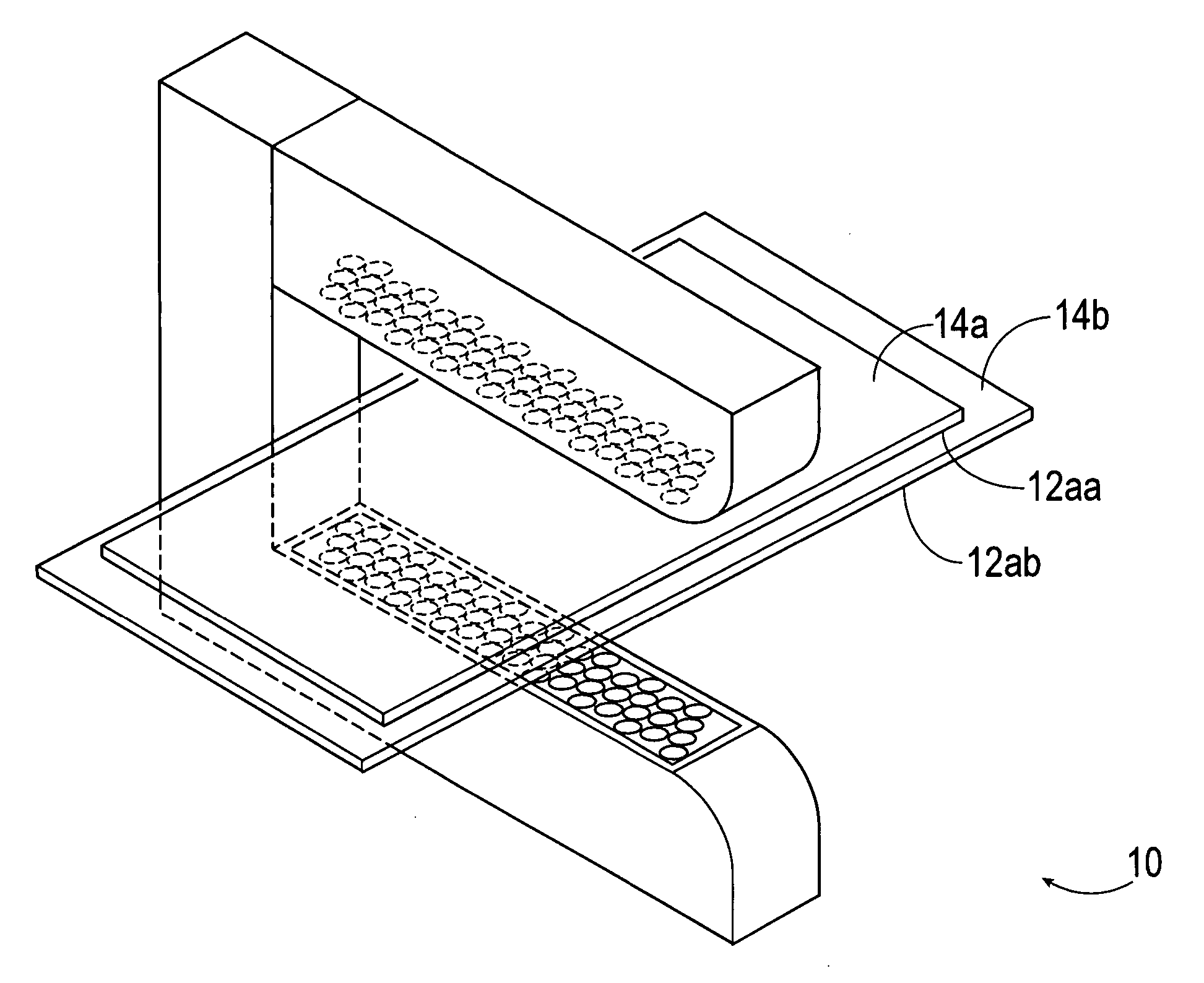
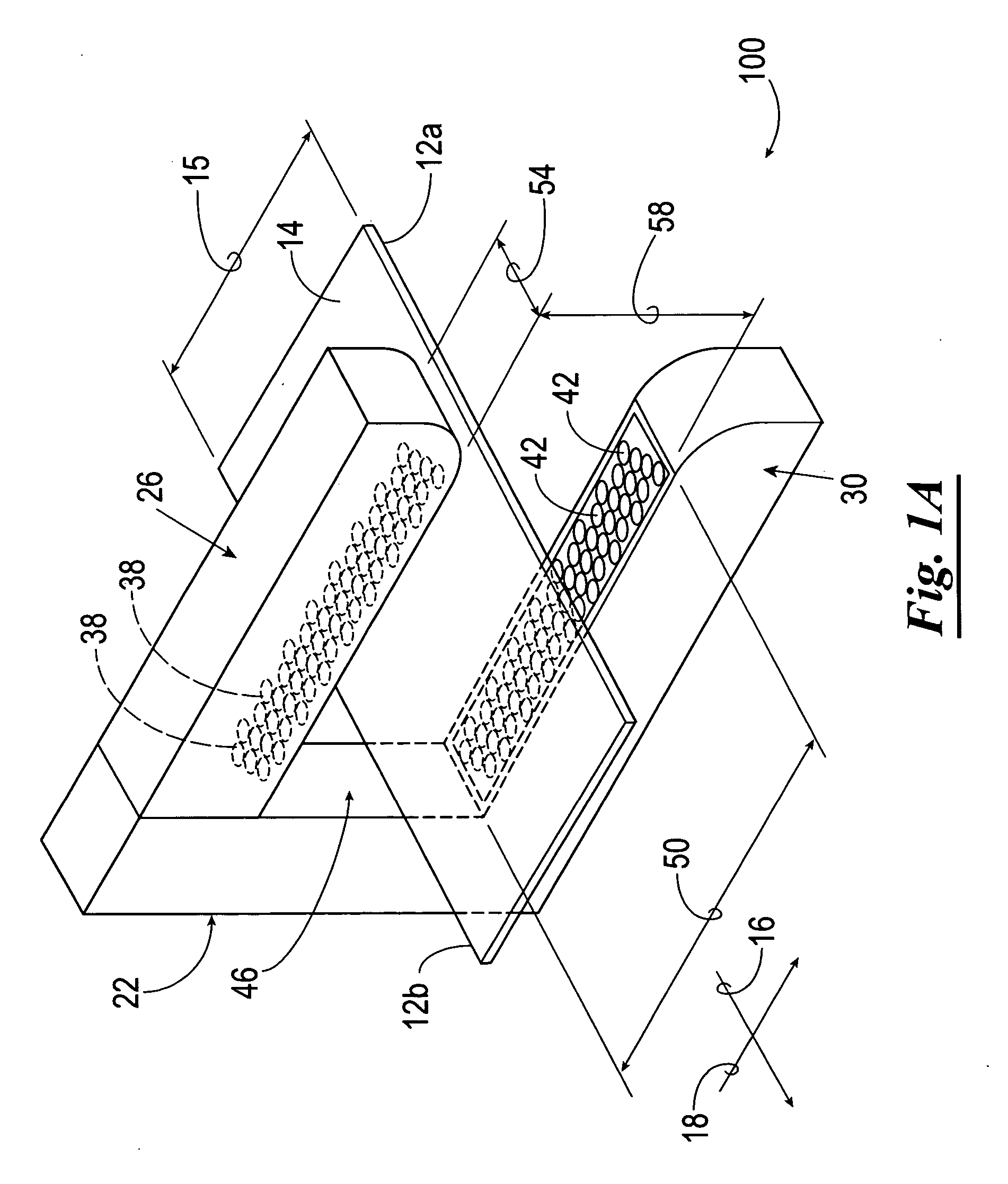
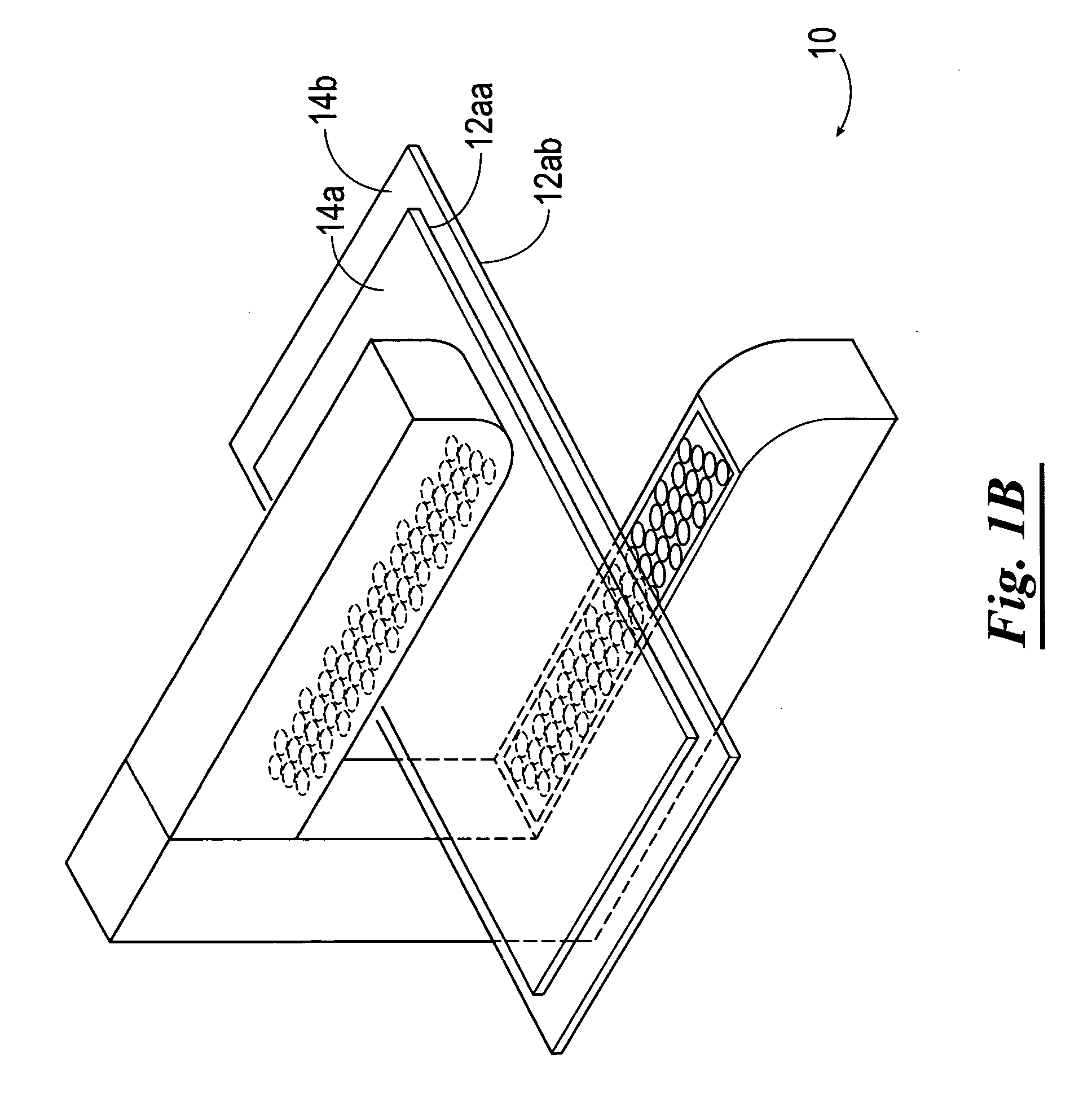
[0042] Referring now to the drawings and in particular to FIG. 1a, shown therein is a sensor system 10 which is constructed in accordance with the present invention. The sensor system 10 is adapted and constructed to accurately sense at least one web material 14 so as to determine the position of at least one edge 12 of the at least one web material 14, a width 15 of the at least one web material 14, a transition between two web materials 14, or combinations thereof. In general, the at least one web material 14 is a continuous sheet of transparent or opaque material moving in a web direction of travel 16, which is generally along the longitudinal axis of the at least one web material 14. As the at least one web material 14 moves along the web direction of travel 16, the at least one web material 14 may deviate in a direction 18, which is generally transverse or lateral to the web direction of travel 16.

[0043] The sensor system 10 includes a housing 22 which is adapted to receive at...


PUM


Abstract

A sensor system for determining the position of at least one edge of at least one web material traveling along a predetermined path. In one embodiment, the sensor system has at least one transmitter block having a plurality of transmitters capable of selectively transmitting ultrasonic signals and at least one receiver block having a plurality of receivers capable of generating receiver output signals in response to the receivers receiving at least a portion of the ultrasonic signals transmitted by the at least one transmitter block. The receiver block is spaced a distance from the transmitter block so as to define a sensor field of view therebetween whereby at least a portion of the at least one web material traveling along a predetermined travel path interferes with at least a portion of the ultrasonic signals transmitted by the at least one transmitter block. The receiver output signals generated by the at least one receiver block is indicative of the position of the web of material as the same is moved along the travel path between the transmitter block and the receiver block. In an alternative embodiment, the functions of the at least one transmitter block and the at least one receiver block are performed essentially equivalently by at least one transceiver block and at least one reflector.

Description

CROSS-REFERENCE TO RELATED APPLICATIONS [0001] Not applicable. BACKGROUND OF THE INVENTION [0002] Ultrasonic sensors having a transmitter disposed on one side of a web material and a receiver disposed on the other side of the web material for locating the position of an edge of the web material therebetween, are known in the art. Such ultrasonic sensors are mounted perpendicular to the web material direction of travel and suffer from problems due to the reflection of sound between the transmitter, the web material, and the receiver. Noise is thereby introduced into the signal produced by the receiver, and reduces the accuracy of the prior art ultrasonic sensors. [0003] Previously, people in the art attempted to solve this problem by changing the angle of the ultrasonic sensor with respect to the web material (away from the perpendicular orientation discussed above), as well as designing sensor housing to maintain non-parallelism between transmit and receive sides, so that the sound ...

Claims


Application Information

Patent Timeline
IPC IPC(8): G01N29/08G01N9/00
CPCB65H23/0204B65H2553/30G01B17/06G01D5/48G01S15/04G01N2291/045G01N2291/048G01N2291/105G01N29/27
Inventor HAQUE, MD M.YATES, JIMPLOETZ, WOLFRAMWINTER, DARCY J.HUEPPELSHEUSER, DALE
Owner MAXCESS AMERICAS INC
Why Eureka
Try Eureka