Apparatus and method for two dimensional magnetron scanning for sputtering onto flat panels

a two-dimensional magnetron and flat panel technology, applied in the field of materials sputtering, can solve the problems of ineffective linear magnetrons, longer deposition periods, and separated magnetrons not being believed to optimally utilize the magnetic fields of constituent magnets, and achieves the effect of increasing uniformity of sputter erosion

Inactive Publication Date: 2006-03-09
APPLIED MATERIALS INC
View PDF34 Cites 23 Cited by
  • Summary
  • Abstract
  • Description
  • Claims
  • Application Information

AI Technical Summary

Benefits of technology

[0008] One aspect of the invention includes a magnetron having a convolute plasma loop, particularly one having a generally rectangular outline. The loop may be arranged in a serpentine shape having parallel straight portions connected by curved portions or in a rectangularized helical shape having straight portions arranged along orthogonal directions. The plasma loop may be formed between an inner magnetic...

Problems solved by technology

As a result, for larger panels having minimum dimensions of greater than 1.8 m, linear magnetrons become increasingly ineffective and require longer deposition periods to uniformly sputter the larger targets and coat the larger substrates.
However, there are several disadvantages to this replication approach.
First, the separated magnetrons are not believed to optimally utilize the magnetic fields of the constituent magnets.
Such high voltages are believed to di...

Method used


Image

  • Apparatus and method for two dimensional magnetron scanning for sputtering onto flat panels
  • Apparatus and method for two dimensional magnetron scanning for sputtering onto flat panels
  • Apparatus and method for two dimensional magnetron scanning for sputtering onto flat panels

Examples


Embodiment Construction

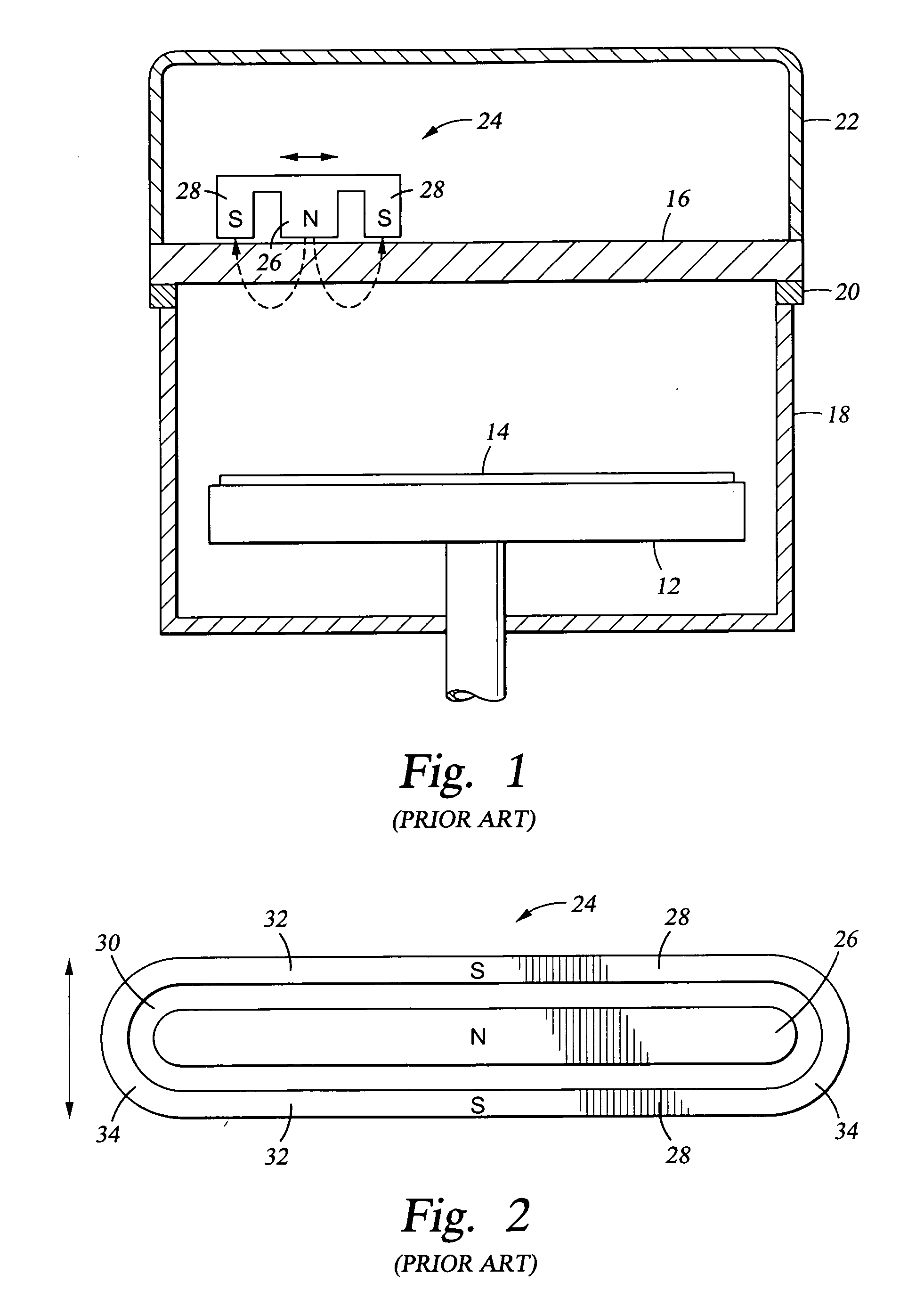
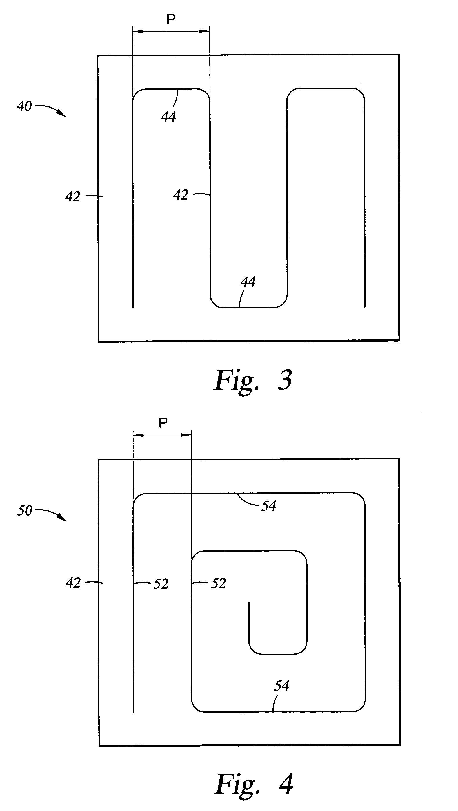
[0042] One aspect of the invention includes shapes for the magnetron that are more convoluted than the linear racetrack of FIG. 2. By convolute is meant a magnetron forming a closed plasma track including curved sections extending in sum over greater than 360° of arc and preferably greater than 7200. In one embodiment illustrated schematically in the plan view of FIG. 3, a serpentine magnetron 40 formed in a magnetron plate 42 includes multiple long parallel straight portions 42 arranged on a pitch P smoothly joined by end portions 44, which may be arc shaped or alternatively short straight portions with curved corners connecting to the straight portions 42. Since the magnetrons described herein are generally shaped to form a closed plasma loop, the illustrated pitch P will be called the loop pitch to distinguish it from a track pitch to be described later. The effective area of the serpentine magnetron 40 defined by the outer generally rectangular outline of the magnetic field dist...


PUM

PropertyMeasurementUnit
Sizeaaaaaaaaaa
Sizeaaaaaaaaaa
Polarityaaaaaaaaaa

Abstract

A rectangular magnetron placed at the back of a rectangular target to intensify the plasma in a sputter reactor configured for sputtering target material onto a rectangular panel. The magnetron has a size only somewhat less than that of the target and is scanned in the two perpendicular directions of the target with a scan length of, for example, about 100 mm for a 2 m target. The scan may follow a double-Z pattern along two links parallel to a target side and the two connecting diagonals. The magnetron includes a closed plasma loop formed in a convolute shape, for example, a rectangularized helix with an inner pole of nearly constant width extending along a single path and having one magnetic polarity completely surrounded by an outer pole having the opposed polarity. External actuators move the magnetron slidably suspended from a gantry which sliding perpendicularly on the chamber walls.

Description

RELATED APPLICATIONS [0001] This application is a continuation in part of Ser. No. 10 / 863,152, filed Jun. 7, 2004, which claims benefit of provisional application 60 / 534,952, filed Jan. 7, 2004. This application also claims benefit of provisional application 60 / 702,327 filed Jul. 25, 2005 and 60 / 705,031 filed Aug. 2, 2005, both incorporated herein by reference.FIELD OF THE INVENTION [0002] The invention relates generally to sputtering of materials. In particular, the invention relates to scanning of the magnetron creating a magnetic field to enhance sputtering from rectangular targets. BACKGROUND ART [0003] Over the past decade, the technology has been intensively developed for fabricating flat panel displays, such as used for computer displays and more recently for television screens. Sputtering is the preferred approach in fabricating flat panels for depositing conductive layers including metals such as aluminum and molybdenum and transparent conductors such as indium tin oxide (I...

Claims


Application Information

Patent Timeline
IPC IPC(8): C23C14/00
CPCH01J37/3408
Inventor TEPMAN, AVI
Owner APPLIED MATERIALS INC
Why Eureka
Try Eureka