
Decontamination and sterilization system using large area x-ray source

Inactive Publication Date: 2006-03-09
CABOT MICROELECTRONICS CORP
View PDF86 Cites 51 Cited by
  • Summary
  • Abstract
  • Description
  • Claims
  • Application Information

AI Technical Summary

Benefits of technology

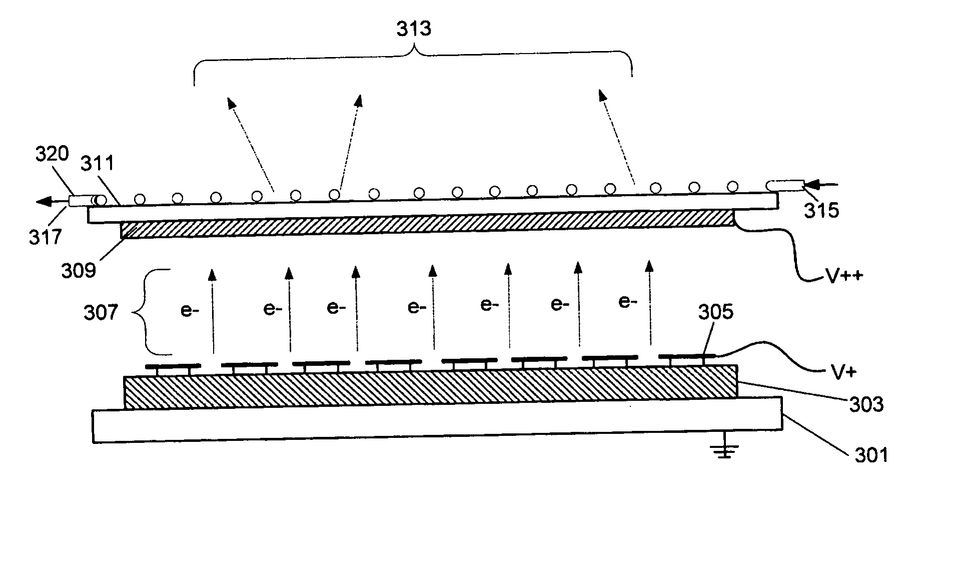
[0007] Embodiments of the invention provide a novel technique for x-ray generation and use. In particular, the treatment system described herein utilizes, according to an embodiment of the invention, one or more large area flat panel sources of x-ray radiation directed into a target zone. A target substance to be treated is placed within the target zone, such as via conveyor belt, pipe, etc., and is irradiated with radiation from the one or more flat panel sources to reduce the biological effects of the contaminant presence in the target substance.
[0009] The use of large area flat panel x-ray sources in the inventive systems allows for decreased installation and operational costs as well as increased efficiency. Additional features and advantages of the invention will be made apparent from the following detailed description of illustrative embodiments which proceeds with reference to the accompanying figures.

Problems solved by technology

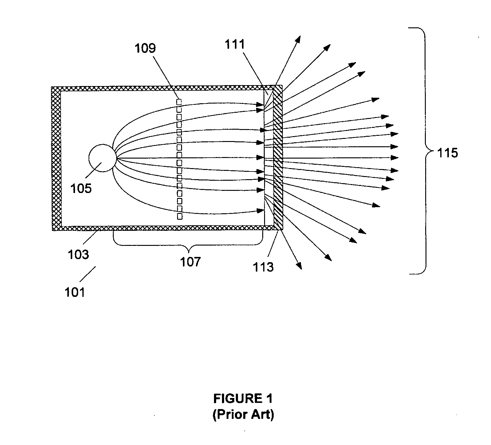
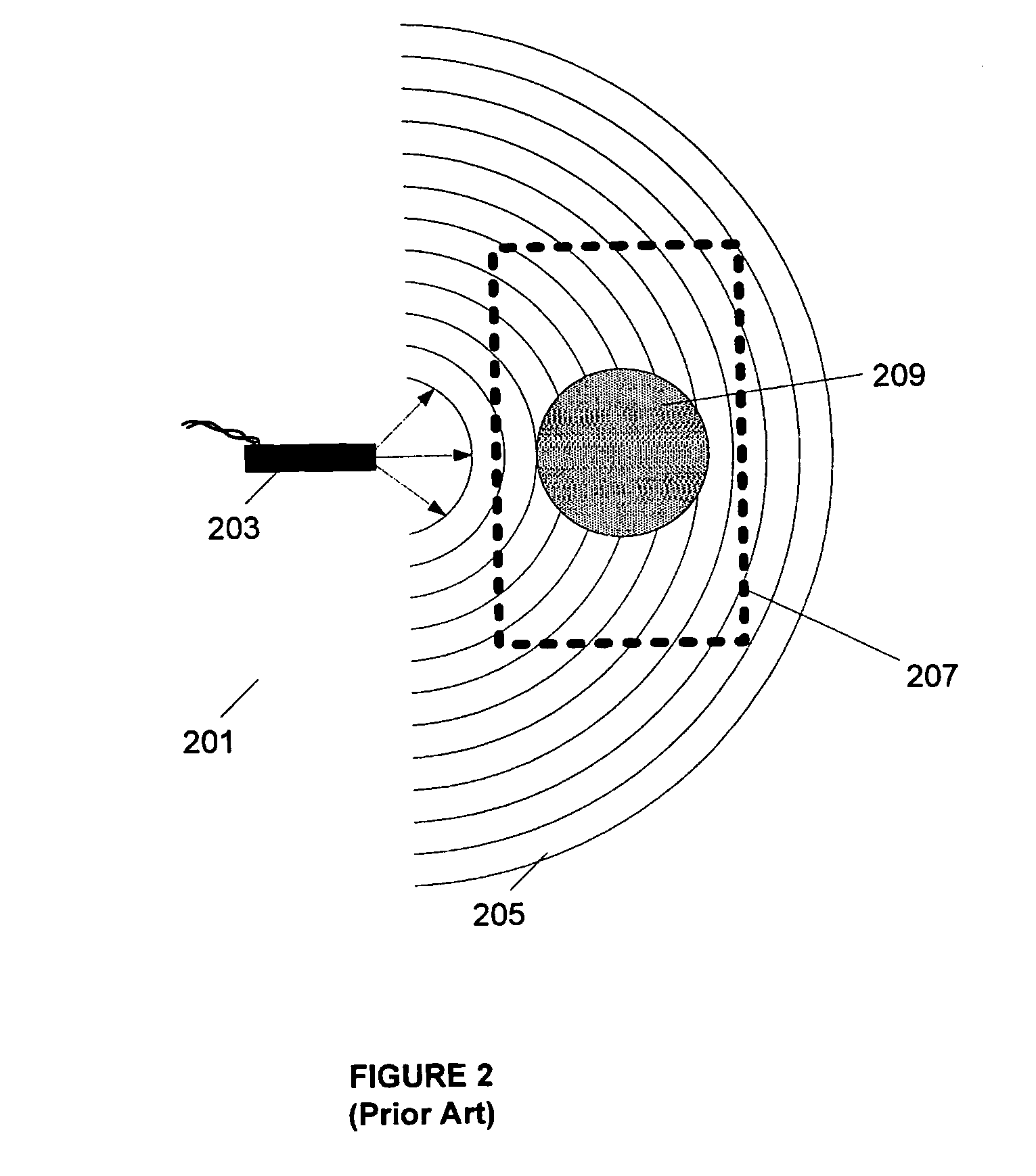
However, as useful as x-rays are in some of these capacities, the efficiency with which that radiation is produced and directed is suboptimal at present.
Although some radiation sources use multiple point sources, or one or more mobile point sources, to make up for the suboptimal emission pattern, such systems have their own inherent drawbacks and complexities.
In particular, complications involving source timing, positioning, etc. are commonplace.

Method used


Image

  • Decontamination and sterilization system using large area x-ray source
  • Decontamination and sterilization system using large area x-ray source
  • Decontamination and sterilization system using large area x-ray source

Examples


Embodiment Construction

[0020] The invention pertains to x-ray generation and use, and encompasses, in embodiments of the invention, a novel system and technique for treating a target substance such as a food item, water, or other material, such as for purposes of decontamination or sterilization. In general overview, an architecture according to an example embodiment of the invention comprises one or more flat panel sources of x-ray radiation adjacent to and / or surrounding a target zone (volume). A target substance is placed within the target zone and is irradiated with radiation from the flat panel source(s) to reduce the effects of contaminants in the target substance. The target substance may reside stationarily within the target zone or may be passed, such as via conveyer, or flowed, such as via radiation transparent tubing, through the zone.

[0021] The systems according to embodiments of the invention are useful for rendering harmless both biological and chemical contaminants in the target substance....


PUM

PropertyMeasurementUnit
Timeaaaaaaaaaa
Widthaaaaaaaaaa
Heightaaaaaaaaaa

Abstract

A novel x-ray treatment system utilizes one or more large area flat panel sources of x-ray radiation directed into a target zone. A target substance within the target zone is irradiated with x-ray radiation from the one or more flat panel sources, reducing the biological effects of a contaminant presence therein. The flat panel source comprises an electron source, an electron accelerator, and an electron target medium. The electron source may emit electrons either via field emission or thermionic emission. The x-ray source may operate in transmissive, reflective, or combined transmissive / reflective mode. The use of large area flat panel x-ray sources in the inventive systems allows for decreased installation and operational costs as well as increased efficiency.

Description

CROSS-REFERENCE TO RELATED APPLICATIONS [0001] This patent application is a continuation-in-part of copending U.S. patent application Ser. No. 10 / 814,714, filed Mar. 31, 2004, by Busta et. al, entitled “Electron Source And Method For Making Same,” which application is herein incorporated by reference in its entirety.FIELD OF THE INVENTION [0002] This invention relates generally to x-ray generation and use, and, more particularly, relates to a large area source for generating x-ray radiation and a system for using same to decontaminate and / or sterilize a target material. BACKGROUND [0003] High-energy electromagnetic radiation in the form of x-rays is used in many areas today. Although the use of x-rays in medical imaging is the most familiar setting to most people, other uses abound as well. For example, x-rays may be used in a medical setting for purposes of activation, such as of a medication or substance, rather than for imaging. Moreover, many uses of x-ray radiation in ground an...

Claims


Application Information

Patent Timeline
IPC IPC(8): G01T1/24A23L5/20A23L5/30C08K3/04
CPCA23L3/263A61L2/08A61L2/082C02F1/30C08F2/54C08K3/04H01J2235/163H01J35/065H01J35/12H01J35/16H01J2235/068H01J2235/087H01J35/04H01J35/116
Inventor BUSTA, HEINZ H.LESIAK, STANLEY D.
Owner CABOT MICROELECTRONICS CORP
Learn More