Display method
a technology of display panel and display panel, applied in the field of display panel, can solve the problems of replacing the display panel based thereon, complex fabrication of such type of liquid crystal display, etc., and achieve the effects of enhancing the spatial utility of various primary colors, not saving fabrication time and cost, and enhancing the spatial utility of display panel
- Summary
- Abstract
- Description
- Claims
- Application Information
AI Technical Summary
Benefits of technology
Problems solved by technology
Method used
Image
Examples
first embodiment
[0033] Referring to FIG. 5, the display 200 includes a backlight module 210 and a display panel 220. The backlight module 210 is suitable to provide three primary color lights, such as red light, blue light and green light. In this embodiment, the backlight module 210 may include a light emitting diode, a cold cathode fluorescent light or other light source suitable for high switching frequency between primary colors. This display panel 220 includes an array of a plurality of pixel regions 222. Each of the pixel regions 222 does not require a color filter thin film. Instead, the arrangement of the liquid crystal is used to determine the transmission rate, and the full color display can be obtained by primary color lights provided by the backlight module 210 transmitting through the liquid crystal with specific transmission rates.
[0034] Referring to FIG. 6, the display method provides a plurality of image data to be displayed by the respective pixel regions within a plurality of con...
second embodiment
[0041] Referring to FIG. 7, the second embodiment differs from the first embodiment by providing at least four primary color lights, while the remaining portions or steps are the same. The description of the same part is thus not repeated again.
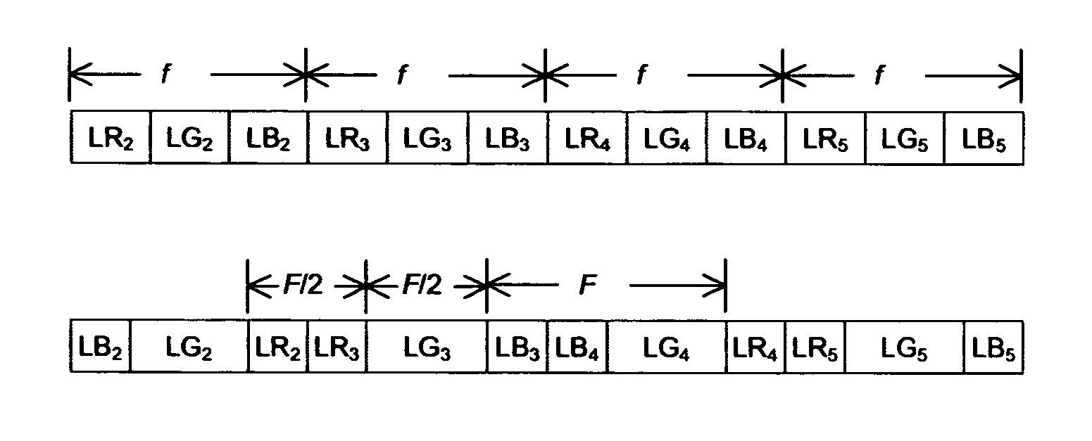
[0042] In this embodiment, the data image to be displayed at each pixel region within a plurality of continuous frame times f are provided. In FIG. 7, four images to be displayed from the second frame time f to the fifth frame time f. Each of the image data includes (L1N, L2N, . . . , LMN), which indicate the brightness of the Mth primary color light to be displayed in the Nth frame time f, where N is a positive integer. In this embodiment, M=4, and L1N, L2N, L3N and L4N are LCN, LRN, LGN and LBN.
[0043] The backlight module provides M-1 types of primary color lights with the first sequence of (1,2, . . . , M-1) and the second sequence (M, M-1, . . . , 2) for the N frame times f. Again, 1, 2, . . . , M-1 indicate the different primary color ...
third embodiment
[0047] Referring to FIG. 8, the third embodiment differs from the second embodiment by the sequence for providing the M-2 types of primary color lights between any two consecutive frame times. The remaining steps of method provided in the third embodiment are the same as those in the second embodiment, such that the repetitive description will not be provided again.
[0048] In this embodiment, M-2 types of primary color lights (R, G) are provided in each of the consecutive frames F with the same sequence.
[0049] In other words, when the display method applied to the backlight module provides five types of primary color lights, the M-2 types of primary color lights are provided to each consecutive frame time with the same or different sequence, which does not have to be opposite or reversed from each other.
[0050] Accordingly, the display methods provided above obtains the full color effect by integrating the primary color backlight, such that the cost and labor required for fabricati...
PUM
 Abstract
Description
Claims
Application Information
 - R&D
- Intellectual Property
- Life Sciences
- Materials
- Tech Scout
- Unparalleled Data Quality
- Higher Quality Content
- 60% Fewer Hallucinations
Browse by: Latest US Patents, China's latest patents, Technical Efficacy Thesaurus, Application Domain, Technology Topic, Popular Technical Reports.
© 2025 PatSnap. All rights reserved.Legal|Privacy policy|Modern Slavery Act Transparency Statement|Sitemap|About US| Contact US: help@patsnap.com


