Device, method and system for determining the road surface condition

a technology of road surface condition and device, applied in the direction of material analysis, instruments,spectrum investigation, etc., can solve the problems of prone to faults and wear, not applicable to the problem of determining the road surface condition at or near a moving vehicle, and no provision for separating reflectan

Inactive Publication Date: 2006-03-09
ELMAN ULF
View PDF7 Cites 32 Cited by
  • Summary
  • Abstract
  • Description
  • Claims
  • Application Information

AI Technical Summary

Benefits of technology

[0009] The invention relates to a device for determining a road surface condition, where the surface condition is one of dry, wet or icy. The device comprises a reflectance spectrometer which senses the reflectance properties of the road at one or several wavelength and uses these reflectance properties to determine the surface condition. The reflectance spectrometer is a wavelength modulation spectrometer, preferably for the near infrared region. The device may wavelength modulate the light being reflected by the surface before or after hitting the surface. The device uses light at a chosen wavelenght, being wavelength modulated at a frequency f, and detects the resulting amplitude modulation of the light at more than one multiple of f, using the amplitude of the amplitude modulations at different multiples of f for determining the road surface condition.
[0010] The device may sense the reflectance properties of a surface at more than one wavelength and use the additional information on the reflectance properties to determine the structural properties of the detected liquid water or ice, i.e. determining whether the water or ice is clear or turbid. This information about the structural properties may be used to assess the slipperiness of the surface.

Problems solved by technology

Older methods for determining the road surface condition using mechanical arrangements are known but are prone to faults and wear.
A number of solutions to the problem of detecting water or ice on a road surface at a fixed position have also been suggested, but are generally not applicable to the problem of determining the road surface condition at or near a moving vehicle.
The method suffers from the drawback that there is no provision for separating reflectance changes occurring due to presence of ice from those occurring due to presence of water on the road surface, or due to changes in the reflectance properties of the asphalt or concrete constituting the road paving.
If the ratio remains within an intermediate level, the method indicates that the road surface is dry, but unfortunately the ratio may also fall within this intermediate range if certain proportions of water and ice are present at the road surface.
Unfortunately, the absorption of light in non turbid media adheres to the Beer-Lambert law, stating that the transmission through the medium decreases exponentially with increasing layer thickness.
For a detection system with finite signal dynamics, this corresponds to a very limited dynamic range in terms of layer thickness variations.
Unfortunately, this implies detecting reflectances at a comparatively large number of wavelengths, necessitating a complex, and therefore expensive arrangement.

Method used


Image

  • Device, method and system for determining the road surface condition
  • Device, method and system for determining the road surface condition
  • Device, method and system for determining the road surface condition

Examples


first embodiment

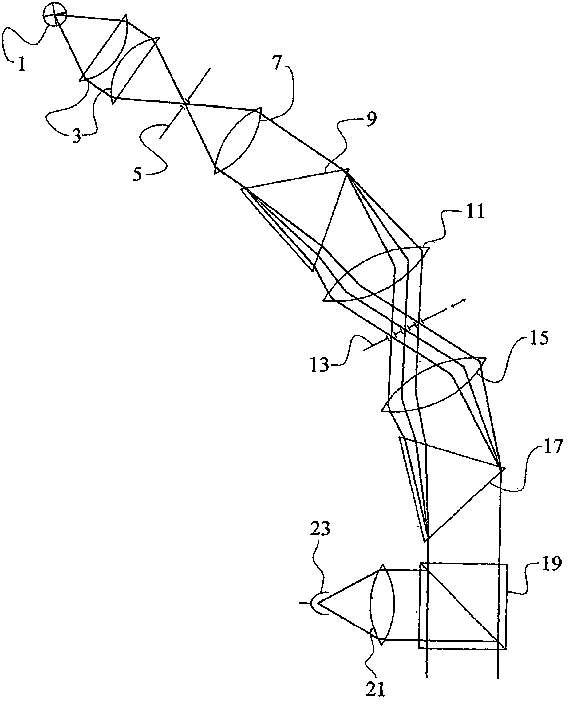
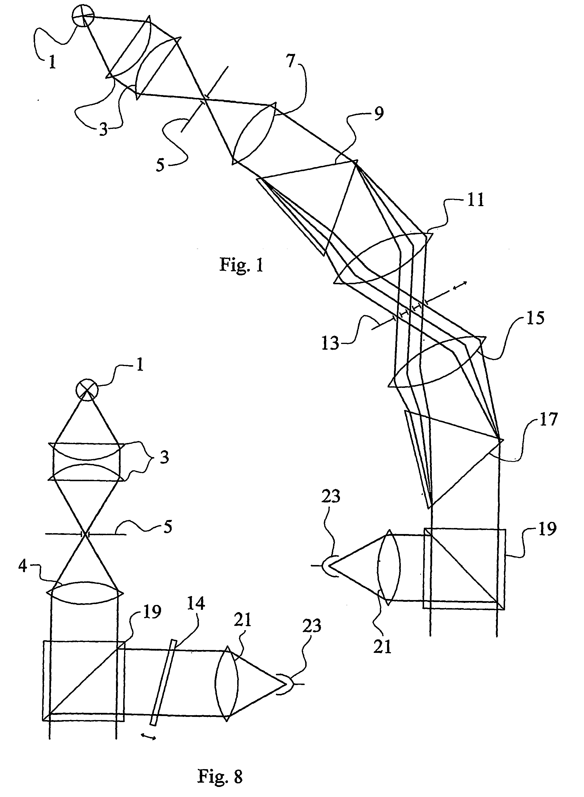
[0020]FIG. 1 shows the ice and water detection device which uses prisms as dispersing elements. The embodiment comprises a light beam emitter with suitable optical properties, constituted by a light source 1, and a first focusing element 3 focusing a portion of the light emitted by the light source on an aperture 5. The light source 1 is schematically shown as an incandescent lamp, and the first focusing element 3 is drawn as a pair of planoconvex lenses, but this is chosen only for illustrating the fundamental function of the device.

[0021] The diverging light beam emitted from the aperture 5 is then transmitted towards a first wavelength selective system. In the wavelength selective system the beam is collimated by a first lens 7, and the collimated beam is directed through a first dispersing prism 9. The light beam transmitted through the prism is dispersed into a range of wavelengths, which are focused by a second lens 11 onto a selection element 13 which only transmits selected ...

second embodiment

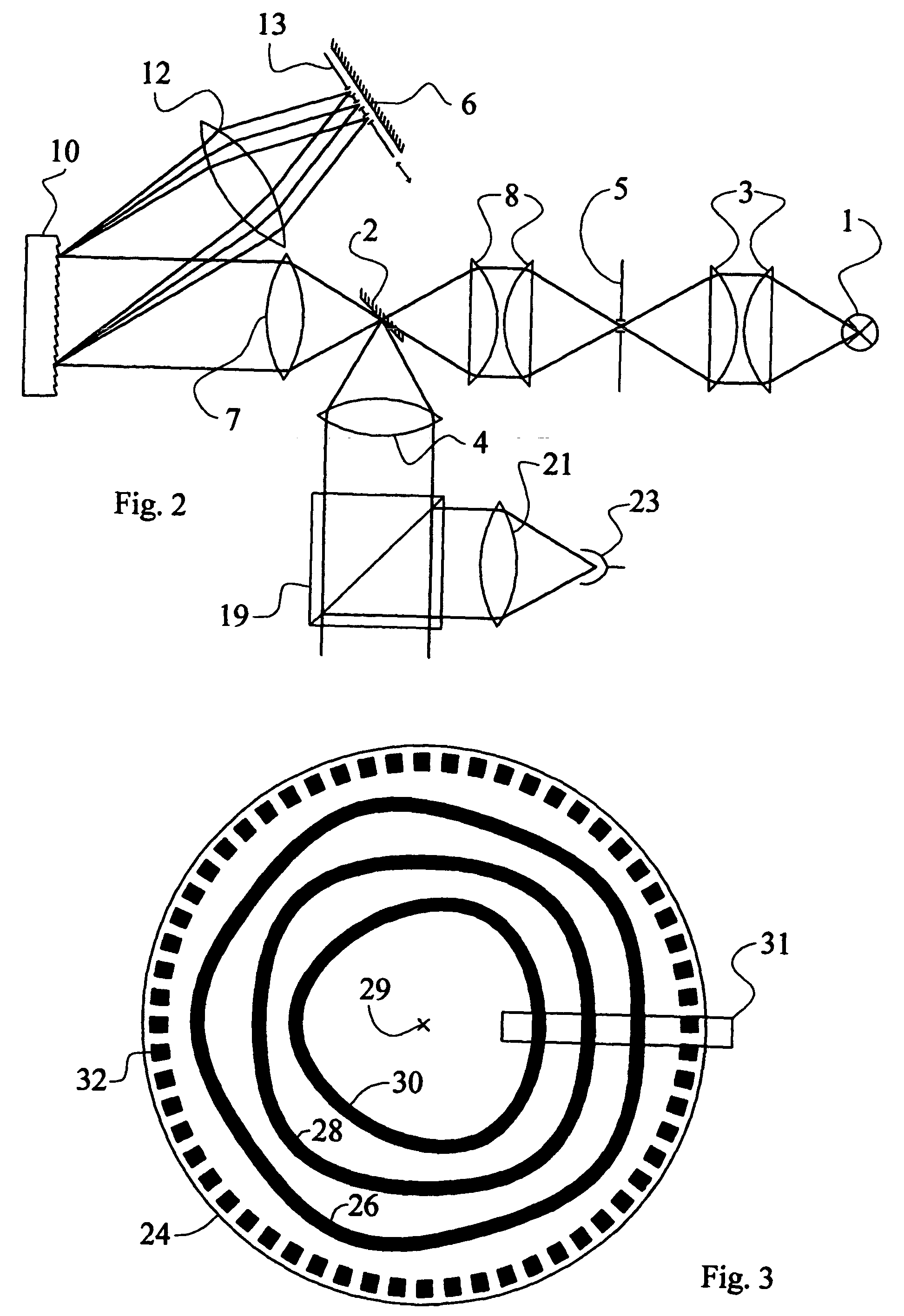
[0024]FIG. 2 shows the detection device which instead of prisms uses reflecting gratings, which have a much higher dispersive power, as dispersing elements. The embodiment comprises a light beam emitter identical to the one in FIG. 1, and the emitted light is focused by a second focusing element 8 drawn as a pair of planoconvex lenses. The focused beam passes, at its focal point, above a first mirror 2 (being positioned in a direction below the paper plane of the figure), and is then directed to a second wavelength selective system.

[0025] In the second wavelength selective system the beam is collimated by a first lens 7, and the collimated beam i directed towards a reflective grating 10. The light beam reflected from the grating is dispersed into a range of wavelengths, which are focused by a fifth lens 12 onto a selection element 13 which only transmits selected segments of the light focused onto it. The selection element 13 is here embodied as a chopper wheel 24, shown in FIG. 3. ...

third embodiment

[0041]FIG. 8 shows the detection device which instead of a dispersive element 9, 10, 17 and a wavelength selection element 13 uses a pivoting dielectric filter 14. Here, the wavelength modulation occurs after the light hitting the road surface has been received by the detection device. To be able to separate light originating from the light beam emitter of the detection device from background radiation, the aperture 5 of the light beam emitter is embodied as the aperture of a chopper wheel for intensity modulation. The result is that amplitude modulated light of a known frequency fA is emitted from the light beam emitter and may be separated from background radiation. The amplitude modulated light is then collimated by a sixth lens 4, partially transmitted through a beam splitter 19, and hits the road surface.

[0042] Light reflected from the road surface hitting the beam splitter 19, is partially reflected by the beam splitter 19 and transmitted in a direction orthogonal to that of t...


PUM

PropertyMeasurementUnit
reflectance spectrometeraaaaaaaaaa
reflectance propertiesaaaaaaaaaa
wavelength modulation spectrometeraaaaaaaaaa

Abstract

The invention relates to a device, a method and a system for determining a road surface condition, where the surface condition is one of dry, wet or icy. The device comprises a reflectance spectrometer which senses the reflectance properties of the road at one or several wavelengths and uses these reflectance properties to determine the surface condition. The reflectance spectrometer is a wavelength modulation spectrometer, preferably for the near infrared region. The system determines the surface condition and indicates it to a user of the system.

Description

[0001] The present invention relates to a system, a device and a method for determining the presence or absence of liquid water or ice according to the introductory portions of the independent claims. In particular, it relates to such a system, device and method using wavelength modulation spectroscopy. BACKGROUND OF THE INVENTION [0002] A number of solutions for solving the problem of determining possible slipperiness of road surfaces, in particular aimed at detecting presence or absence of water or ice on the road surface, are known. Older methods for determining the road surface condition using mechanical arrangements are known but are prone to faults and wear. A number of solutions to the problem of detecting water or ice on a road surface at a fixed position have also been suggested, but are generally not applicable to the problem of determining the road surface condition at or near a moving vehicle. For that problem, remote sensing methods using spectroscopical methods have be...

Claims


Application Information

Patent Timeline
Patent Type & Authority Applications(United States)
IPC IPC(8): G01N21/47G01N21/35G01N21/55G08B19/02
CPCG01N21/359G01N21/55G08B19/02G01J3/0229G01J3/4338G01J3/0208G01N21/3554
Inventor ELMAN, ULF
Owner ELMAN ULF
Why Eureka
Try Eureka