
Ultra-high pressure discharge lamp unit and light source apparatus

a technology of ultra-high pressure discharge and light source, which is applied in the direction of point-like light sources, lighting and heating devices, transportation and packaging, etc., can solve the problems of reducing the life of discharge lamps, reducing and reducing the efficiency of discharge lamps. , to achieve the effect of reducing the risk of discharge lamps, and reducing the cost of discharge lamps

Inactive Publication Date: 2006-03-09
PHOENIX ELECTRIC CO
View PDF7 Cites 20 Cited by
  • Summary
  • Abstract
  • Description
  • Claims
  • Application Information

AI Technical Summary

Benefits of technology

The present invention provides an ultra-high pressure discharge lamp unit that can achieve both enhanced brightness and prolonged lifetime. It uses an ultra-high pressure discharge lamp and allows a pressure difference to result between the exterior and the interior of the reflector, which prevents the lamp from exploding. The unit includes a reflector with a concave reflective surface and a translucent cover fitted over an opening portion of the reflector. The reflector has a sidewall with an exhaust vent hole opening into an air passage defined along the external surface of the reflector. The air passage is narrowed by a duct, which increases the flow rate of air and results in a further reduced pressure. The ultra-high pressure discharge lamp has a discharge tube in which mercury is encapsulated at a high pressure and has a bulb wall loading of 0.8 W / mm2 or more, which ensures enhanced heat dissipation. The ultra-high pressure discharge lamp unit can be used in a light source apparatus with an air passage defined along the external surface of the reflector and a fan for supplying air to the air passage. The narrowing of the air passage by the duct results in an increased flow rate of air, which causes heated air within the reflector to be discharged out of the reflector more rapidly. The ultra-high pressure discharge lamp unit can suppress a temperature rise within the reflector and prevent the lamp from exploding.

Problems solved by technology

Conventionally, it has been difficult to dissipate heat from the interior of the reflector toward the exterior because of the cover fitted over the opening portion of the reflector and, hence, the temperature of the discharge lamp is elevated too much.
This results in the discharge lamp having a shortened lifetime contrary to the demand for prolonged lifetime.
Particularly where the discharge lamp is reduced in size for enhanced brightness, this problem is conspicuous because the temperature within the reflector is easy to rise.

Method used


Image

  • Ultra-high pressure discharge lamp unit and light source apparatus
  • Ultra-high pressure discharge lamp unit and light source apparatus
  • Ultra-high pressure discharge lamp unit and light source apparatus

Examples


Embodiment Construction

[0032] The present invention will now be described in detail with reference to the accompanying drawings.

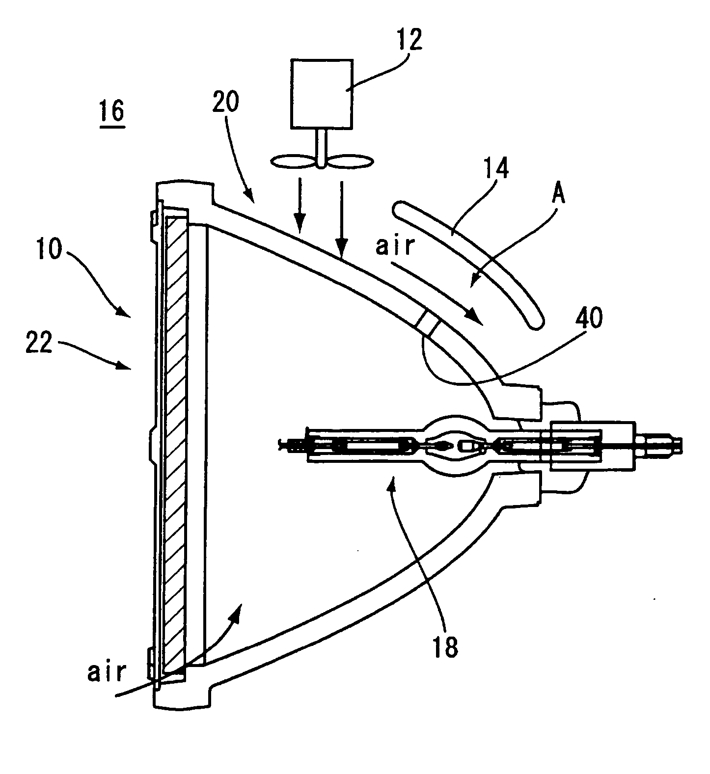
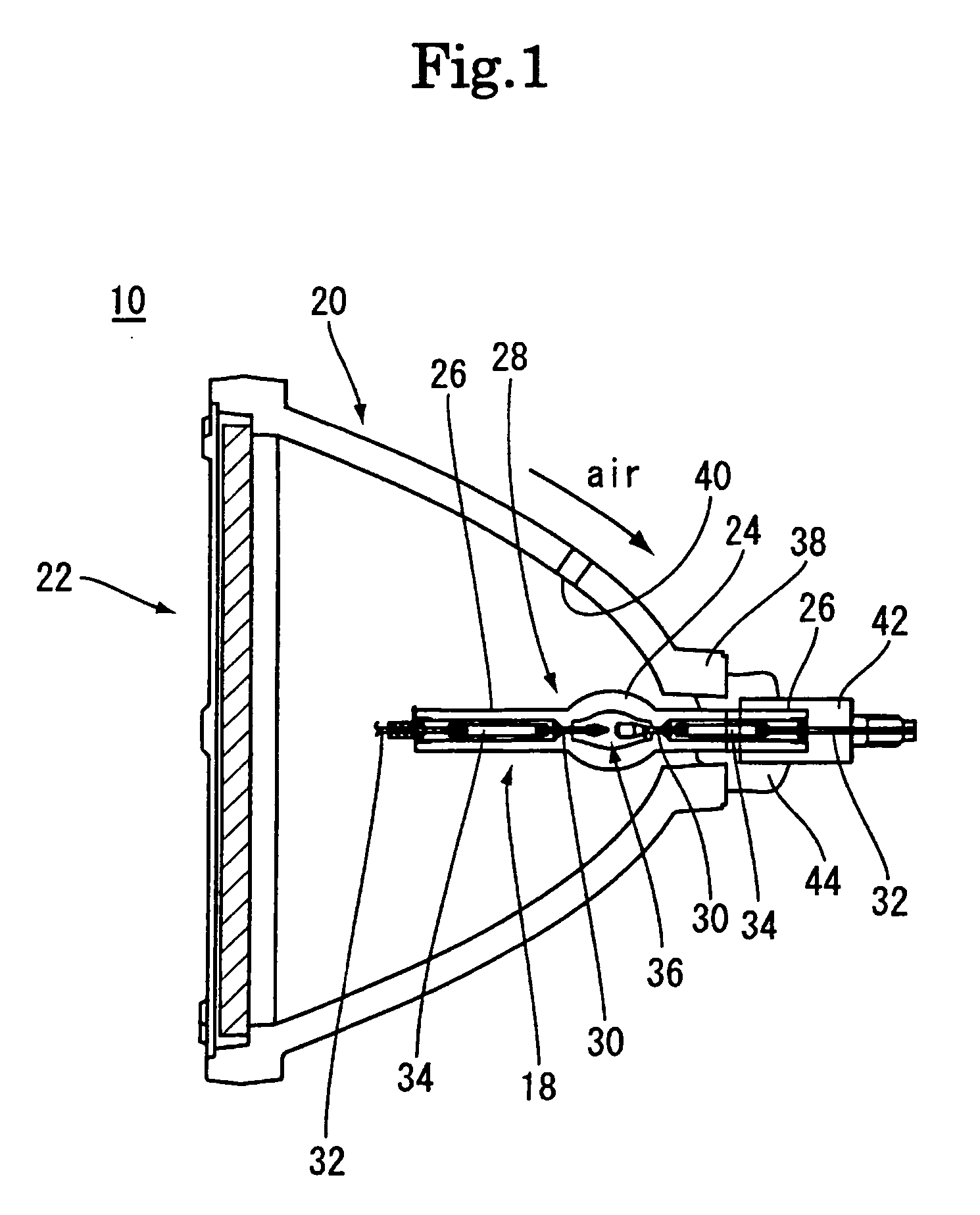
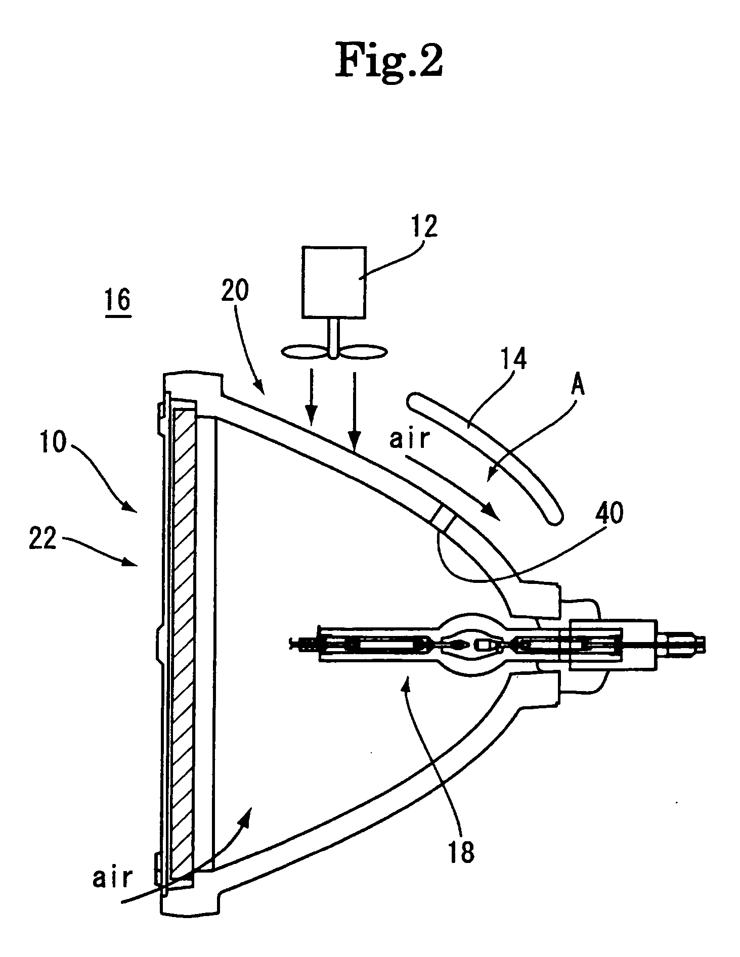
[0033] Ultra-high pressure discharge lamp unit 10 shown in FIG. 1 cooperates with a fan 12 and an air guide 14 to form a light source apparatus 16 for use in a projector, as shown in FIG. 2. The ultra-high pressure discharge lamp unit 10 includes an ultra-high pressure discharge lamp 18, a reflector 20 for reflecting light emitted from the ultra-high pressure discharge lamp 18, and a cover 22.

[0034] As shown in FIG. 1, the ultra-high pressure discharge lamp 18 includes a discharge tube 28 of quarts glass having a light-emitting bulb 24 and sealing portions 26 extending straight from opposite ends of the light-emitting bulb 24. In each of the sealing portions 26 are accommodated an electrode pin 30, a lead pin 32 and molybdenum foil 34 electrically interconnecting the electrode pin 30 and the lead pin 32. The end of each electrode pin 30 situated within the light-emitting bulb 2...


PUM


Abstract

An ultra-high pressure discharge lamp unit is provided which satisfies both of the demand for enhanced brightness and the demand for prolonged lifetime. The ultra-high pressure discharge lamp unit includes: a reflector having a concave reflective surface; an ultra-high pressure discharge lamp; and a translucent cover, the reflector having sidewall defining an exhaust vent hole opening into an air passage defined to extend along an external surface of the reflector. When air flows through the air passage, a flow rate difference results between the exterior and the interior of the reflector and, hence, the pressure exerted on the exterior along which air flows at a higher flow rate becomes lower than that exerted on the interior. Accordingly, heated air within the reflector is discharged out of the reflector through the exhaust vent hole by suction caused by the relatively low pressure.

Description

BACKGROUND OF THE INVENTION [0001] 1. Field of the Invention [0002] The present invention relates to an ultra-high pressure discharge lamp unit and a light source apparatus, which are for use in a projector configured to project information displayed by an imaging device through a projection optical system. [0003] 2. Description of the Related Art [0004] In recent years, projectors are being used in various scenes such as business presentation, home theater, and rear projection TV. A light source apparatus used as a principal component of such a projector usually includes a discharge lamp unit having a discharge lamp fitted to a reflector having a concave reflective surface. [0005] Such a light source apparatus is strongly desired to have enhanced brightness. Conventionally, such a demand has been satisfied by using an increased pressure discharge lamp (made by encapsulating mercury at a pressure of 0.15 mg / mm3 or more within the lamp) or a discharge lamp of a reduced size (having a...

Claims


Application Information

Patent Timeline
Patent Type & Authority Applications(United States)
IPC IPC(8): F21V29/00F21Y101/00
CPCF21V29/02F21V29/00F21V29/67F21V29/83H01J61/523
Inventor NAKAGAWA, ATSUJIIKEDA, TOMIHIKO
Owner PHOENIX ELECTRIC CO
Learn More