Hearing-aid interconnection system

a technology of interconnection system and abutment, which is applied in the direction of transducer casing/cabinet/support, medical science, dentistry, etc., can solve the problems of hindering the passage of bacteria from the inside of the abutment through the interconnection to the skin penetrating area, and achieves the effect of reducing the force on the sensitive bone-fixture interface, reducing sealing pressure, and facilitating removal

Active Publication Date: 2006-03-09
OTICON MEDICAL
View PDF3 Cites 49 Cited by
  • Summary
  • Abstract
  • Description
  • Claims
  • Application Information

AI Technical Summary

Benefits of technology

[0015] In a preferred embodiment at least one of the contact surfaces has an axial angle greater than 0 degrees and smaller than 30 degrees. Usually the angle would be chosen to be ≧0 degrees but it is also possible to have a contact surface with an angle less than 0 degrees. The advantage of having and angle that is ≧0 degrees, is that the press contact and the sealing will be located to a more peripheral portion of the interface between the fixture and the abutment without offering gaps for bacteria. Preferably, the angle should be less than 30 degrees to accomplish a sufficient sealing pressure between the abutment and the fixture. The axial angle of the contact surface on the abutment has however to be in matching relationship with the axial angle of the contact surface on the fixture, otherwise there might be no press fit between the fixture and the abutment.
[0016] A non-matching relationship might for example result in a fit where the abutment initially is hard to press down on to the fixture but where the abutment then gets fully loose around the fixture when it has been fully pressed down on to the fixture. The choice of the actual angles that represent a matching relationship is for example also depending on the measures and elasticity of the material in the abutment and fixture. The angle, measures and material of the contact surfaces may be either chosen so that a quite firm press fit between the abutment and the fixture is achieved or so that the abutment can be more easily removed from the fixture.
[0017] At least one of the contact surfaces can preferably have a circular geometry. To get a firm press fitting and to get a long inner thread in the fixture it is advantageous to have a significantly protruding portion in the lateral end of the fixture. To accommodate the protruding fixture portion the depth of the abutment cavity is specifically greater than 1 mm in one of the preferred embodiments.
[0018] In another preferred embodiment the protruding fixture portion includes a male hexagonal geometry which can be used both

Problems solved by technology

Also, the possibilities for bacteria to pass from the inside of the abutment vi

Method used


Image

  • Hearing-aid interconnection system
  • Hearing-aid interconnection system
  • Hearing-aid interconnection system

Examples


Embodiment Construction

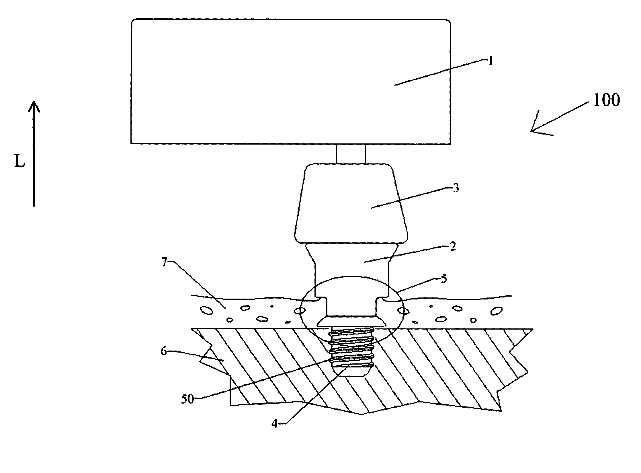
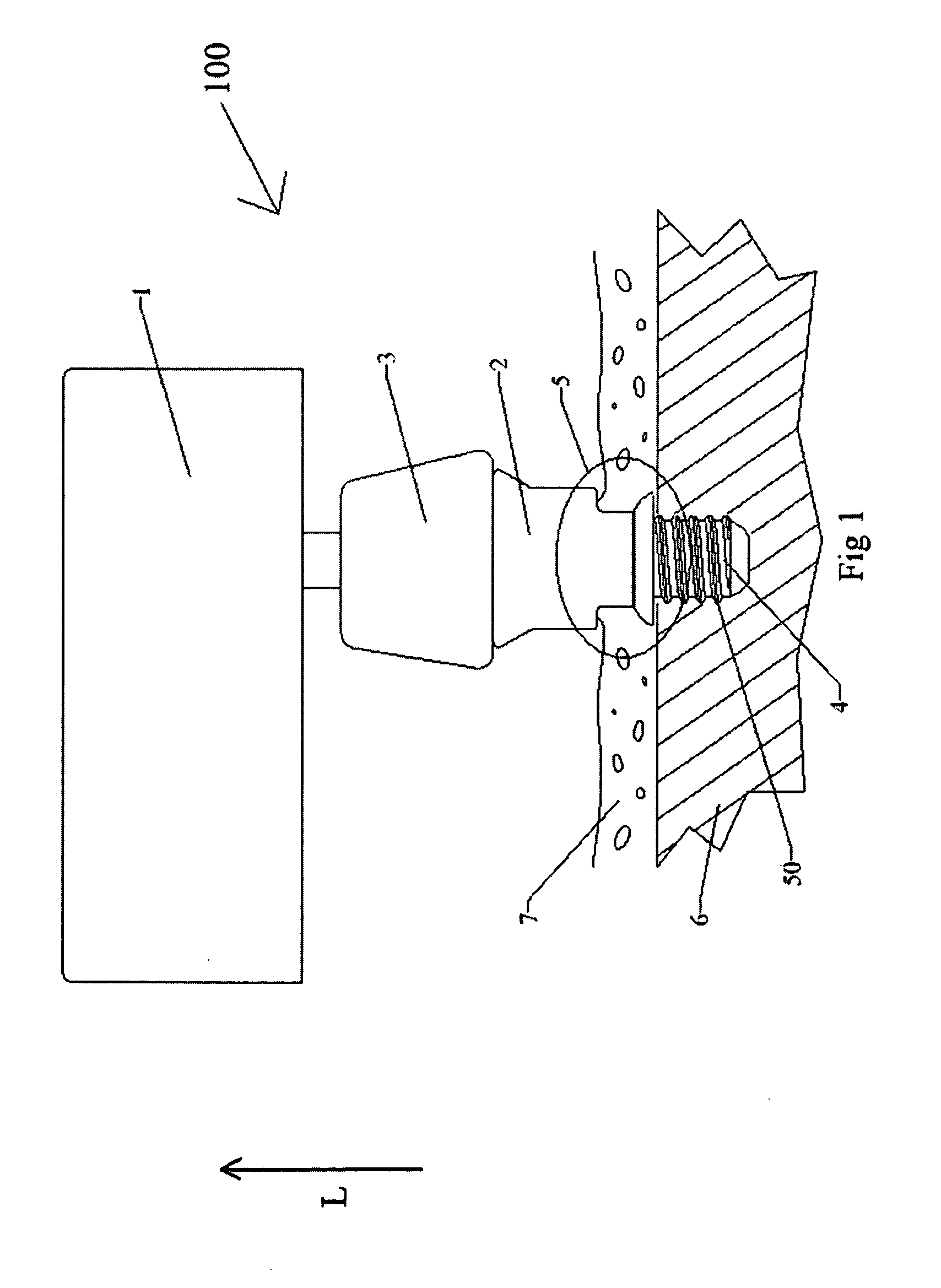
[0034]FIG. 1 shows an overview of a bone anchored hearing aid system 100 of the present system. A hearing aid device 1 is connected to a hearing aid abutment 2 via a coupling 3. The coupling may be removably connected to the abutment 2 and to the hearing-aid device 1. The abutment 2 is connected to a fixture 4 via an interconnection 5. The fixture may have a threaded portion 50 that is anchored in the skull bone 6. The abutment 2 may go through the skin 7. When the system 100 is properly mounted to a skull bone 6, vibrations are transmitted from the hearing aid device 1 to the skull bone 6 and the patient can then hear via bone conduction. A lateral direction may be defined by the arrow (L) that is parallel to an axial direction of the interconnection.

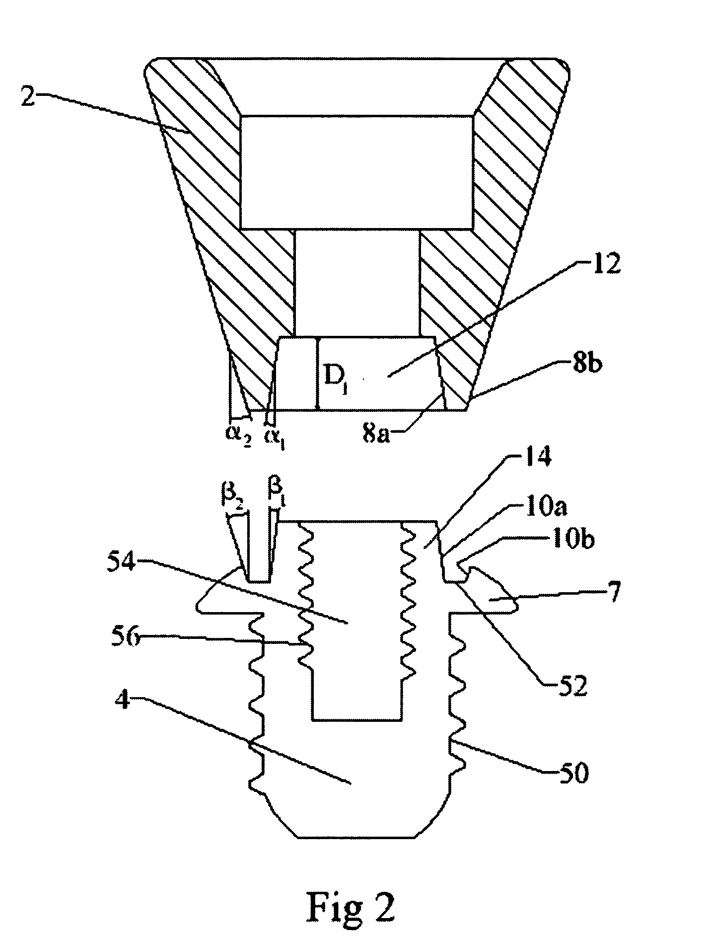
[0035]FIG. 2 is a cross-sectional side view of a separated hearing aid abutment 2 and a fixture 4 of a preferred embodiment. The fixture 4 has an outwardly protruding flange 7 that has a circular upper cavity 52 defined therein by con...


PUM


Abstract

The hearing-aid interconnection system has a skin-penetrating hearing-aid abutment (2) and a fixture (4) anchored in a skull bone (6). A first press fit is formed between a first contact surface (8a) of the abutment and a first fixture contact surface (10a) of the fixture. The first abutment contact surface extends around the first fixture contact surface. A second press fit is formed between a second contact surface (8b) of the abutment and a second fixture contact surface (10b) of the fixture. The second fixture contact surface extends around the second abutment contact surface.

Description

TECHNICAL FIELD [0001] The present invention relates to a hearing-aid interconnection system between a bone anchored fixture and a skin penetrating hearing aid abutment. BACKGROUND OF THE INVENTION [0002] Bone anchored hearing aids are essential for the rehabilitation of patients suffering from hearing losses for which traditional hearing aids are insufficient. The most common type of such devices consists of an external hearing aid with a vibrating transducer which, through a coupling, is connected to a skin-penetrating abutment which has an interconnection to a screw shaped fixture anchored in the skull bone. The fixture is usually made of titanium and is usually designed with a flange to prevent the fixture from being pushed through the skull bone in case of a sudden accidental impact. The surgery for anchoring the fixture and the abutment is often done in one stage where the fixture and the abutment are inserted at the same time. However, for some patients it is necessary to do ...

Claims


Application Information

Patent Timeline
IPC IPC(8): A61C3/00H04R25/00
CPCH04R2460/13H04R25/606
Inventor WESTERKULL, PATRIK
Owner OTICON MEDICAL
Why Eureka
Try Eureka