Image forming apparatus

Active Publication Date: 2006-03-09
CANON KK
View PDF4 Cites 17 Cited by
  • Summary
  • Abstract
  • Description
  • Claims
  • Application Information

AI Technical Summary

Benefits of technology

[0013] An object of the invention is to realize the silence and the electric power saving by suppressing cooling unit action a

Problems solved by technology

However, when the number of rotations of the fan is controlled based on the detection temperature detected by the temperature detection means as described above, because the temperature is detected near a position where the temperature detection means is installed, it is difficult to grasp the temperature of a component for which cooling is actually required in the image forming apparatus.
On the other hand, because the temperature exceeds 200° C. during the printing in the fixing device which is of the heat source in the image forming apparatus, as shown in FIG. 8, the sheet discharging roller holder exceeds the heat-resistant temperature when t

Method used


Image

  • Image forming apparatus
  • Image forming apparatus
  • Image forming apparatus

Examples


Example

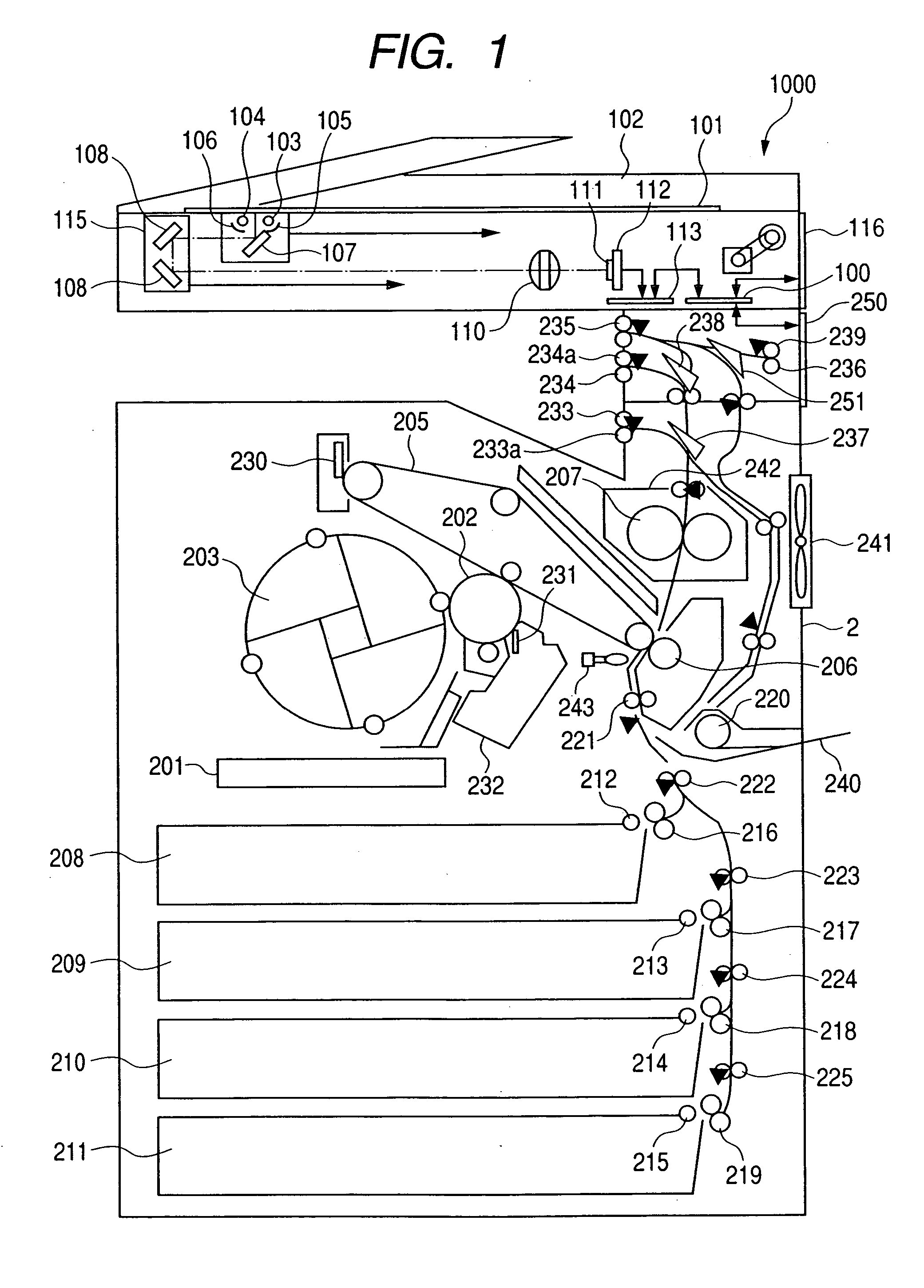
[0026]FIG. 1 is a block diagram schematically showing a full-color image forming apparatus which is of an image forming apparatus according to a first embodiment of the invention.

[0027] Referring to FIG. 1, a full-color image forming apparatus 1000 includes a color reader portion 1 and a color printer portion 2.

[0028] First a configuration of the color reader portion 1 will be described. The reference numeral 101 denotes an original plate (platen), and the reference numeral 102 denotes an automatic document feeder (ADF). It is also possible that a mirror-surface pressing plate or white pressing plate (not shown) is attached instead of the ADF 102. The reference numerals 103 and 104 denote a light source which lights an original. A halogen lamp, a fluorescent tube, a xenon lamp, and the like are used as the light sources 103 and 104. The reference numerals 105 and 106 denote a light reflector which condenses the light from the light sources 103 and 104 onto the original. The refere...


PUM


Abstract

A full-color image forming apparatus has a cooling fan switchable between rotating speeds of “full speed” and “half speed.” A transfer portion thermistor is installed near a photosensitive drum and an intermediate transfer member, and a printer control portion controls the rotating-speed switching of a cooling fan based on the temperature detected by the transfer portion thermistor. The printer control portion sets the rotating speed of the cooling fan at “half speed” when print job is started, sets a fan speed switching threshold value at 25° C. during the print job of only the single-side printing, sets the fan speed switching threshold value at 30° C. during a duplex print job, and switches the cooling fan to “full speed” when the detection temperature is higher than the set fan speed switching threshold value.

Description

BACKGROUND OF THE INVENTION [0001] 1. Field of the Invention [0002] The present invention relates to an image forming apparatus and a control method thereof and a program. [0003] 2. Related Background Art [0004] Conventionally, in the image forming apparatus such as a copying machine, a printer, and a facsimile which are an electrophotographic type using toner during image forming, a fan is attached to the image forming apparatus in order to exhaust heat and air to the outside of the image forming apparatus. The number of rotations (or rotating speed) of the fan is controlled in order to suppress problems, such as noise and power consumption increase, caused by the attachment of the fan. [0005] For example, Japanese Patent Application Laid-Open No. 2003-270890 discloses a method of changing the number of rotations of the fan depending on color image printing and monochrome image printing. [0006] Japanese Patent Application Laid-Open No. 2004-117732 discloses a method, in which tempe...

Claims


Application Information

Patent Timeline
IPC IPC(8): G03G21/20
CPCG03G21/206G03G2215/00084
Inventor OKA, YUSHI
Owner CANON KK
Why Eureka
Try Eureka