Differential unit

a technology of differential units and units, applied in mechanical equipment, transportation and packaging, gearing, etc., can solve the problems of abnormal noise generation, and increase of weight and siz

Inactive Publication Date: 2006-03-09
TOCHIGI FUJI IND CO LTD
View PDF10 Cites 33 Cited by
  • Summary
  • Abstract
  • Description
  • Claims
  • Application Information

AI Technical Summary

Benefits of technology

[0041] Accordingly, it is possible to arrange both the actuators within the bearing span of the differential case, and it is possible to entirely form the unit compact while securing the supporting rigidity of the differential case.

Problems solved by technology

Accordingly, there is actually a risk that an increase of weight and an increase of size are generated.
Further, when the differential rotational force having an excessive load is input the multiple disc friction clutch slips, and there is a risk that an abnormal noise is generated (for example, refer to Japanese Unexamined Patent Publication No. 2000-240685 and Japanese Unexamined Patent Publication No. 2003-232432).

Method used


Image

  • Differential unit
  • Differential unit
  • Differential unit

Examples


first embodiment

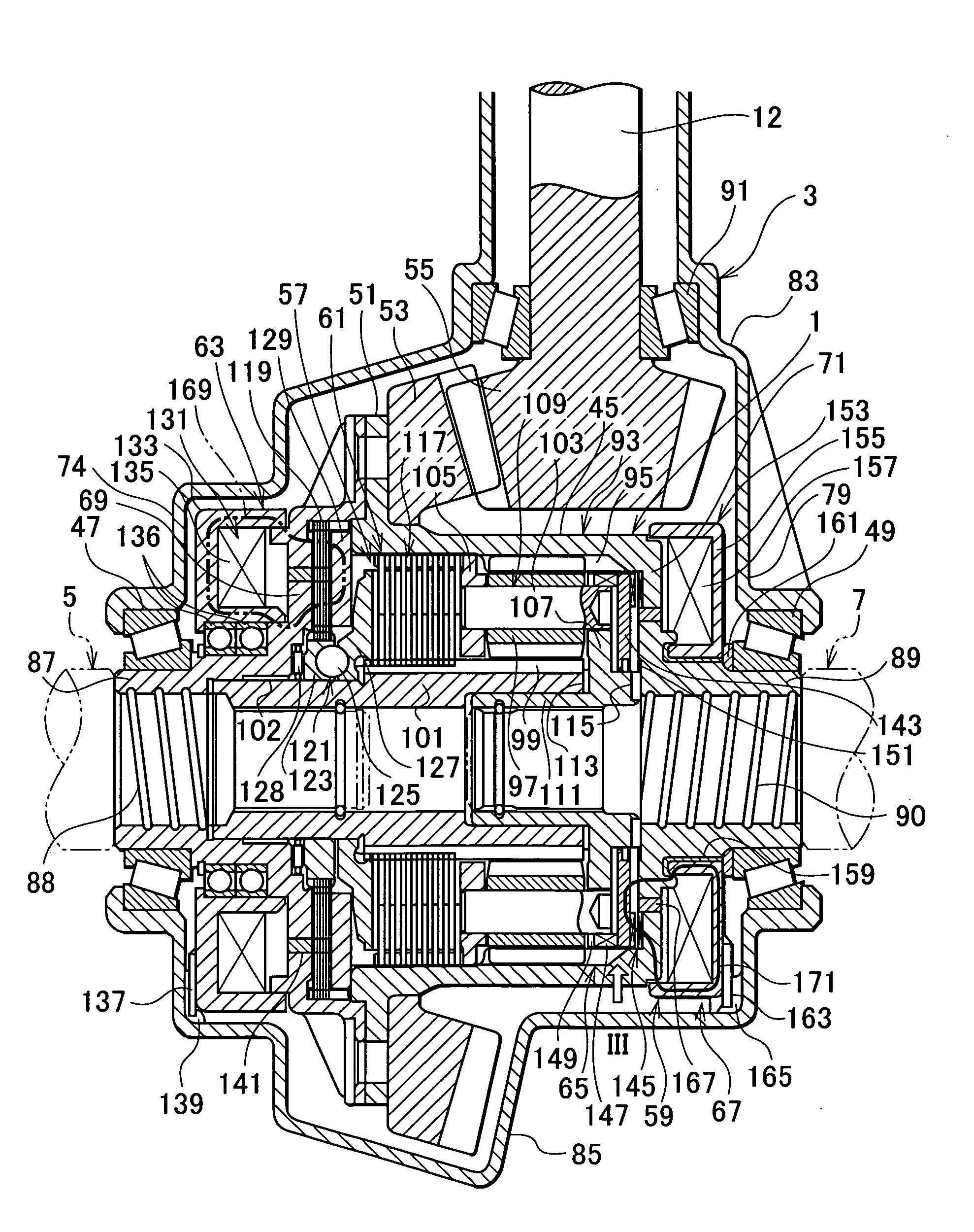
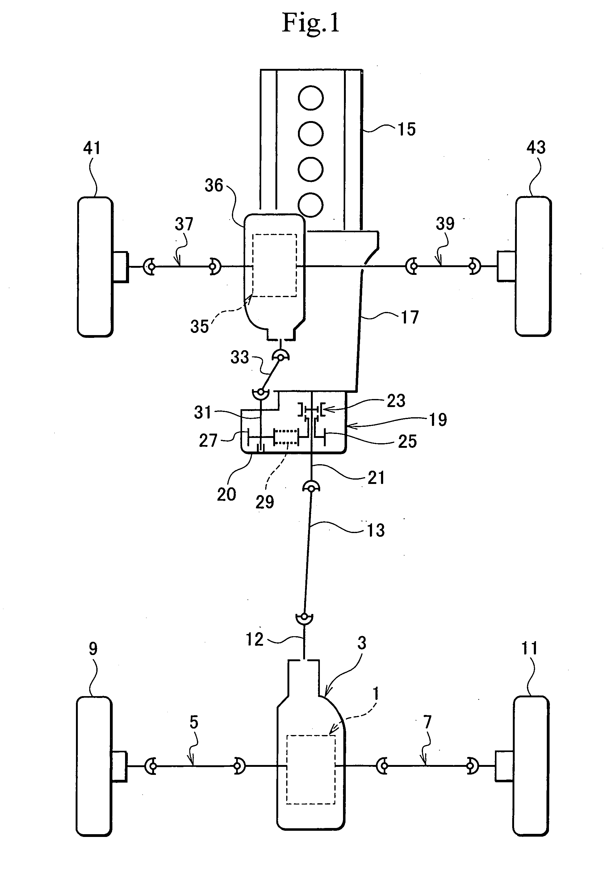
[0056]FIG. 1 is a skeleton plan view of a four-wheel drive vehicle to which an first embodiment according to the present invention is applied. A differential unit in accordance with the first embodiment of the present invention is applied, for example, as a rear differential unit 1, and is rotatably supported to a differential carrier 3. The rear differential unit 1 is connected and interlocked to left and right rear wheels 9 and 11 via left and right axle shafts 5 and 7.

[0057] A rotational force of a propeller shaft 13 is input to the rear differential unit 1 via a drive pinion shaft 12. A rotational force is transmitted to the propeller shaft 13 from an engine 15 via a transmission 17 and a transfer 19.

[0058] A trans on shaft 21 is supported to a transfer case 20 of the transfer 19. The transmission shaft 21 is provided with an interrupting mechanism 23 and a sprocket 25. A chain 29 is wound around the sprocket 25 with respect to the other sprocket 27. The sprocket 27 is fixed t...

second embodiment

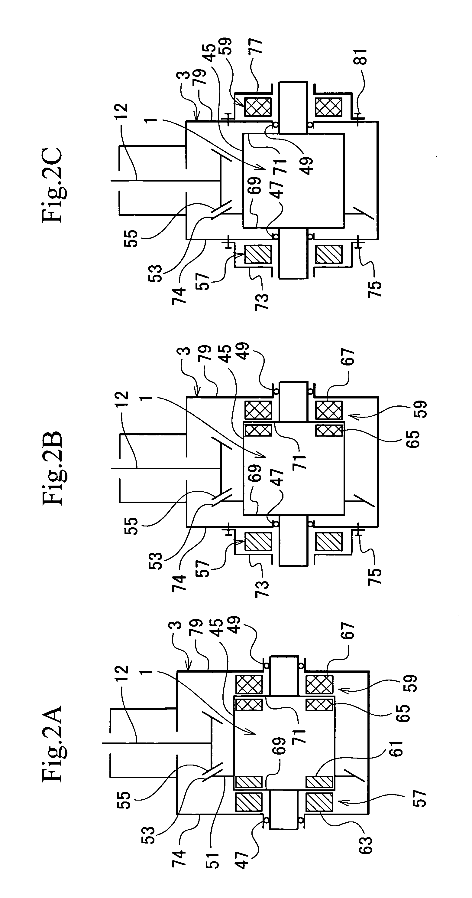
[0119]FIG. 4 is a cross sectional view of a rear differential unit and a periphery thereof according to a second embodiment. The present embodiment corresponds to FIG. 2A, and a basic structure is the same as that of the first embodiment in FIG. 3. In the following explanation of the second embodiment, elements corresponding to those of the first embodiment are represented with like reference numerals or like reference numerals with A.

[0120] As shown in FIG. 4, in the present embodiment, a bevel gear-type mechanism is applied as a differential mechanism 93A, and limiting clutches 117Aa and 117Ab are divisionally interposed between a differential case 45A and left and right side gears 173 and 175 side, respectively.

[0121] The differential mechanism 93A includes side gears 173 and 175, a pinion shaft 177, and a pinion gear 179. Both side gears 173 and 175 are engaged with the pinion gear 179 rotatably supported to the pinion shaft 177. The axle shafts 5 and 7 are connected to the si...

third embodiment

[0137]FIGS. 5A and 5B are views according to third embodiment of the present invention. FIG. 5A is a cross sectional view of a differential unit and a periphery thereof, and FIG. 5B is an explanatory view showing an engagement of a limiting actuator with respect to a differential carrier. The present embodiment corresponds to FIG. 2B. However, in accordance with the present embodiment, the differential lock mechanism is arranged within the receiving cover, in place of the differential lock mechanism. In this case, basic structures of the differential unit and the differential limiting mechanism are approximately the same as those of the second embodiment in FIG. 4. In the following explanation of the third embodiment, elements corresponding to those of the second embodiment are represented with like reference numerals or like reference numerals with B or like reference numerals with B in place of A.

[0138] As shown in FIG. 5A, in a differential unit 1B in accordance with the present...


PUM


Abstract

The invention provides a differential unit which can be arranged in compact as a whole, while a differential limit and a differential lock are appropriately executed. The differential unit is provided with a differential mechanism transmitting from a differential case (45) to a pair of axle shafts a rotational force while allowing a differential rotation, and is provided with a differential limiting mechanism (57) which can limit the differential rotation, and a differential lock mechanism (59) which can lock up the differential rotation. The differential limiting mechanism (57) is provided with a limiting actuator (63) for operation, the differential lock mechanism (59) is provided with a lock actuator (67) for operation, and the limiting actuator (63) and the lock actuator (67) are independently arranged in both sides of the differential case (45).

Description

BACKGROUND OF THE INVENTION [0001] 1. Field of the Invention [0002] The present invention relates to a differential unit which can execute a differential limit and a differential lock. [0003] 2. Description of the Related Art [0004] In a conventional differential unit there is a structure which controls to fasten a multiple disc friction clutch on the basis of an electromagnetic force so as to limit a differential rotation of the differential unit. In this differential unit it is possible to obtain an appropriate handling property in correspondence to, for example, a weather condition, a road surface condition and a traveling condition in an on-road state, by controlling a differential limit force generated by the multiple disc friction clutch in correspondence to traveling conditions. [0005] In an off-road traveling, there is a case that the differential rotation of the differential unit is locked up in accordance with a demand of an accomplishing property. At this time, in the dif...

Claims


Application Information

Patent Timeline
Patent Type & Authority Applications(United States)
IPC IPC(8): F16H48/06F16H48/08F16H48/22F16H48/34F16H48/38
CPCF16H48/08F16H48/10F16H48/22F16H48/24F16H2048/346F16H48/34F16H48/40F16H2048/085F16H48/30
Inventor TERAOKA, MASAO
Owner TOCHIGI FUJI IND CO LTD
Why Eureka
Try Eureka