

Endoprosthesis comprising a magnesium alloy
- Summary
- Abstract
- Description
- Claims
- Application Information
AI Technical Summary
Benefits of technology
Problems solved by technology
Method used
Image

Examples
Embodiment Construction
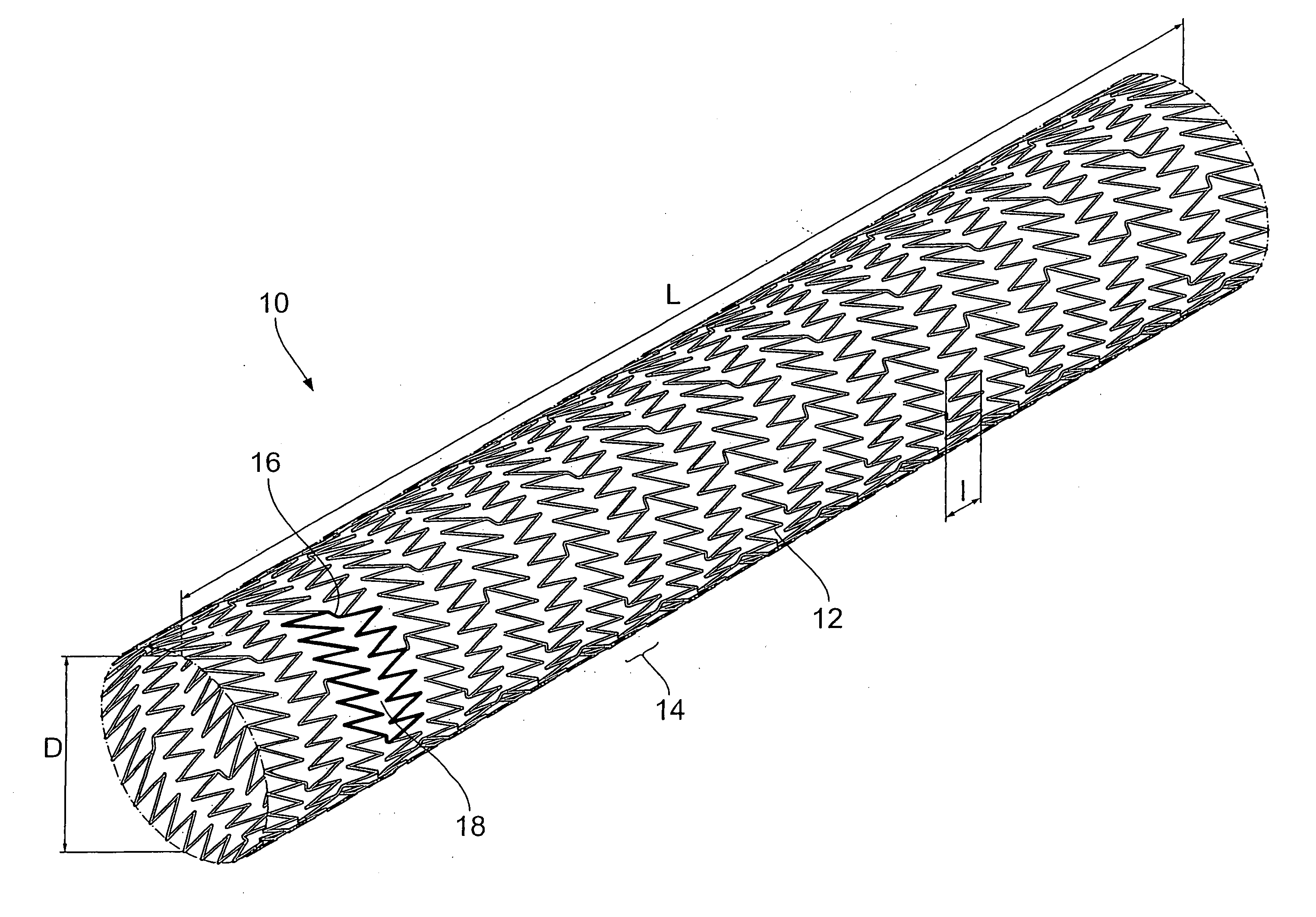
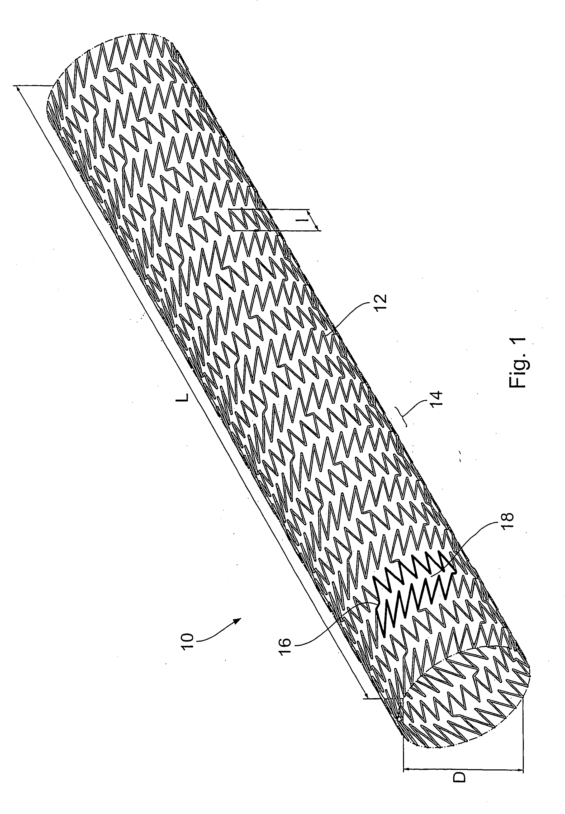
[0049]FIG. 1 shows an endoprosthesis as an endoluminal prosthesis in the form of a stent 10 having a carrier structure. The stent 10 and its carrier structure are in the form of a hollow body which is open at its ends and the peripheral wall of which is formed by the carrier structure which in turn is formed by partially folded legs 12. The legs 12 form support portions 14 which are each formed by a leg 12 which is closed in an annular configuration in the longitudinal direction and which is folded in a zig-zag or meander-shaped configuration. The stent 10 is suitable for coronary use.
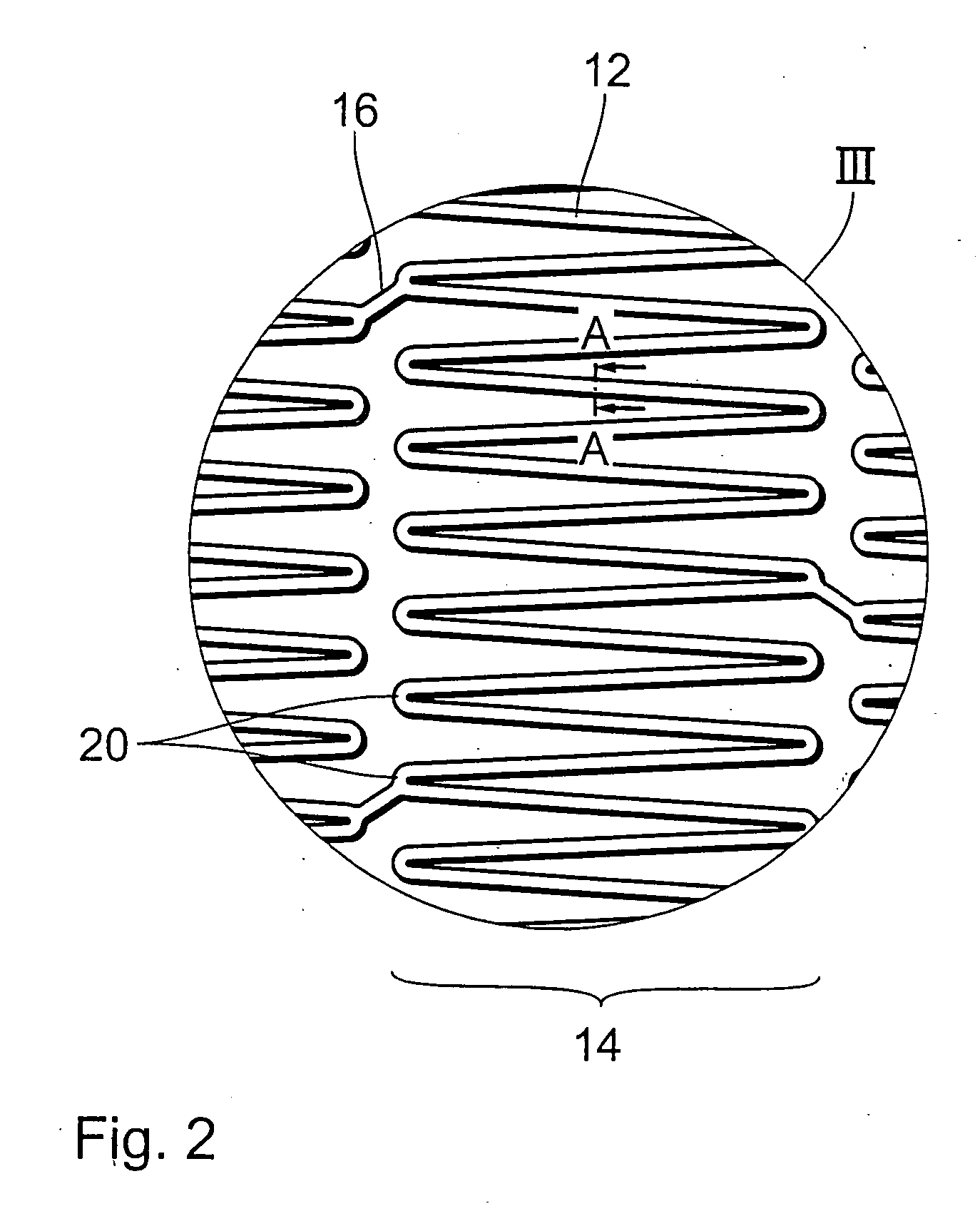
[0050] The carrier structure of the stent 10 is formed by a plurality of such support portions 12 which occur in succession in the longitudinal direction. The support portions or leg rings 14 are connected together by way of connecting legs 16. Each two connecting legs 16 which are mutually adjacent in the peripheral direction and the parts, which are in mutually opposite relationship between those co...
PUM
 Abstract
Description
Claims
Application Information