
System for acquiring data from facilities and method

a technology for acquiring data and facilities, applied in the field of systems for acquiring data from facilities and methods, can solve the problems of inability to accurately measure pressure, the inability to use master-slave communication protocols, and the inability to achieve accurate pressure measurement, etc., and achieve the effect of low cost and convenient installation

Inactive Publication Date: 2006-03-09
ZEDI CANADA
View PDF17 Cites 78 Cited by
  • Summary
  • Abstract
  • Description
  • Claims
  • Application Information

AI Technical Summary

Benefits of technology

The system provides accurate, flexible, and timely data acquisition and notification, enhancing monitoring and management of oil and gas production facilities with improved pressure measurement accuracy and simplified installation, enabling remote access and robust alarming capabilities.

Problems solved by technology

However, these SCADA systems suffer from a variety of deficiencies.
A significant deficiency is related to the inherent limitations of the Master-Slave communication protocol that is employed by SCADA systems.
Further, prior art systems communicate from a limited number of oil and gas facilities to a single monitoring station which in turn relays information to a central control station.
Another limitation in current practice is the accuracy of pressure measurement, which is impaired by ambient temperature fluctuations.
This accuracy limitation reduces the effectiveness in many process monitoring applications that depend on measurement stability, such as process simulation or process accounting.
A further limitation of current practice is the elaborate installation requirements that result from the physical size, number of components and complex interconnections that are needed to implement each field location with a remote measurement system.

Method used


Image

  • System for acquiring data from facilities and method
  • System for acquiring data from facilities and method
  • System for acquiring data from facilities and method

Examples


Embodiment Construction

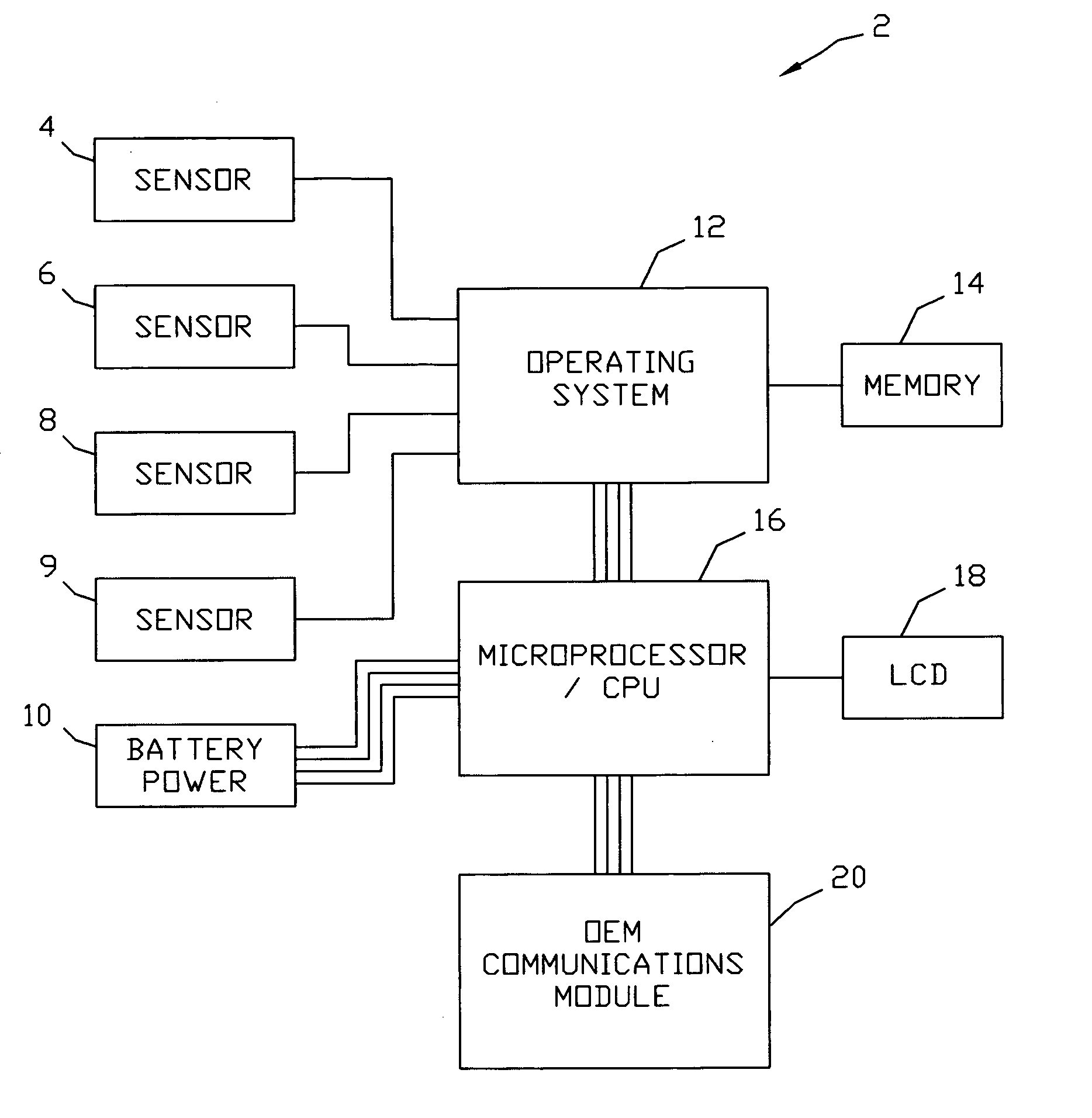
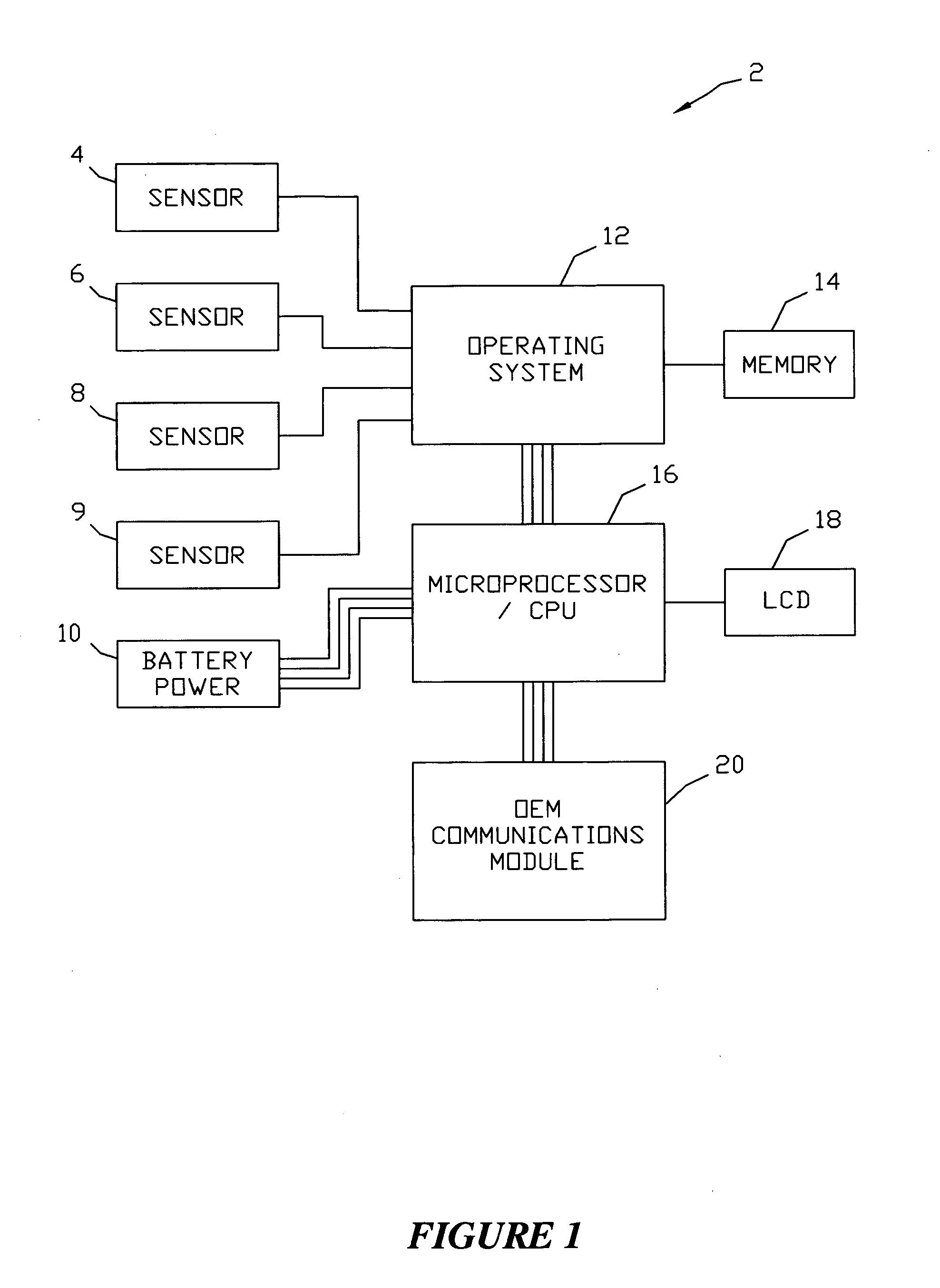
[0052] Referring now to FIG. 1, a schematic flow chart depicting the basic components of the field instrument 2 (FI) of the present invention will now be described. In a most preferred embodiment, the FI 2 is a very high accuracy pressure instrument designed specifically for use in the oil and gas industry. In the embodiment shown, two analog pressure sensors 4, 6 will be included within the enclosure.

[0053] The sensor core is a high accuracy, silicon crystal, strain gauge which has been laser welded into a high pressure autoclave fitting adapter, which in turn is threaded into one of the housing ports located on the enclosure. This sub-assembly is rated for pressures up to 12,000 psi, and has an over-pressure rating of 1.3. Suitable pressure sensors 4, 6 are commercially available from Z. I. Probes, Inc. located in Canada under the mark # 14095140 Pressure Sensor.

[0054] An auxiliary analog sensor port is included in the enclosure to attach to a low accuracy external resistive bas...


PUM


Abstract

A field instrument and system for obtaining pressure, flow and temperature data from a facility. The field instrument includes an enclosure having an opening therein. An integrated analog sensor is sealingly contained within the opening. The field instrument further contains an external analog sensor. An analog to digital converter converts the analog signals to digital readings. An external digital sensor is also provided, with the digital output being communicated through a second opening within the enclosure. A control member that receives, stores and processes the digital readings is positioned within the enclosure. A communication module is included to transmit the digital readings to a remote computer. The communication module allows for two way communication between the field instrument and remote computer. The remote computer may be a server that allows for access by many users. The communication module also allows for locally accessing the digital readings via a serial port to a local terminal.

Description

[0001] This is a continuation-in-part application of the patent application filed 13 Jan. 2000 as Ser. No. 09 / 482,415, entitled “System for Acquiring Data from a Facility and Method”.BACKGROUND OF THE INVENTION [0002] This invention relates to a system for obtaining pressure, flow and temperature data from one or more facilities. More particularly, but not by way of limitation, the invention relates to a system having one or more instruments that collect, process and store measurements of pressure, flow and temperature and relays data to a remotely located network data receptor series, where for example it may be accessed by multiple users. [0003] In the production of oil and gas from subterranean reservoirs, operators have found it necessary to complete wells in many remote regions. In order to produce, transport and refine hydrocarbons, it is necessary to construct production facilities at these remote regions. Due to the hazardous nature of hydrocarbons, it is necessary to employ...

Claims


Application Information

Patent Timeline
Patent Type & Authority Applications(United States)
IPC IPC(8): G06F11/00G06F15/00E21B43/00F16K37/00G01D9/00G05B23/02
CPCF16K37/0091G01D9/005
Inventor ITO, TOKUBENTERUD, KEVINDO, ROBERTJARMAN, ANDREW
Owner ZEDI CANADA
Learn More