Fiber laden energized fluids and methods of use thereof

a technology of energized fluids and fibers, applied in fluid removal, chemistry apparatus and processes, borehole/well accessories, etc., can solve the problems of increased resource and material requirements, poor proppant placement, increased polymer damage to the formation, etc., and achieve good proppant suspension and transport properties. , excellent gas phase stability

Active Publication Date: 2006-03-16
SCHLUMBERGER TECH CORP
View PDF18 Cites 119 Cited by
  • Summary
  • Abstract
  • Description
  • Claims
  • Application Information

AI Technical Summary

Benefits of technology

[0009] The present invention provides aqueous oilfield treatment fluids containing a gas component and fibers. The fluids may further include a

Problems solved by technology

In some cases, however, depending upon specific subterranean formation conditions or job designs, energized fluids may not have high enough viscosity to achieve optimum proppant transportation and suspension, thereby resulting in poor proppant placement.
Increased levels of viscosifying agent, or s

Method used


Image

  • Fiber laden energized fluids and methods of use thereof
  • Fiber laden energized fluids and methods of use thereof

Examples


examples

Viscoelastic Surfactant (VES) Fluid Example

[0042] A viscoelastic surfactant (VES) fluid example was prepared in a 1 liter warring blender, by mixing the following ingredients:

IngredientWeight %Propane-1,2-diol13.4Propan-2-ol20.4Water5.1Erucyl bis-(2-Hydroxyethyl) Methyl Ammonium Chloride61.1

[0043] The resultant VES fluid was then used to prepare examples of aqueous viscoelastic fluids as set forth below.

examples a through l

VES Fluids Containing a Gas Component With and Without Fibers

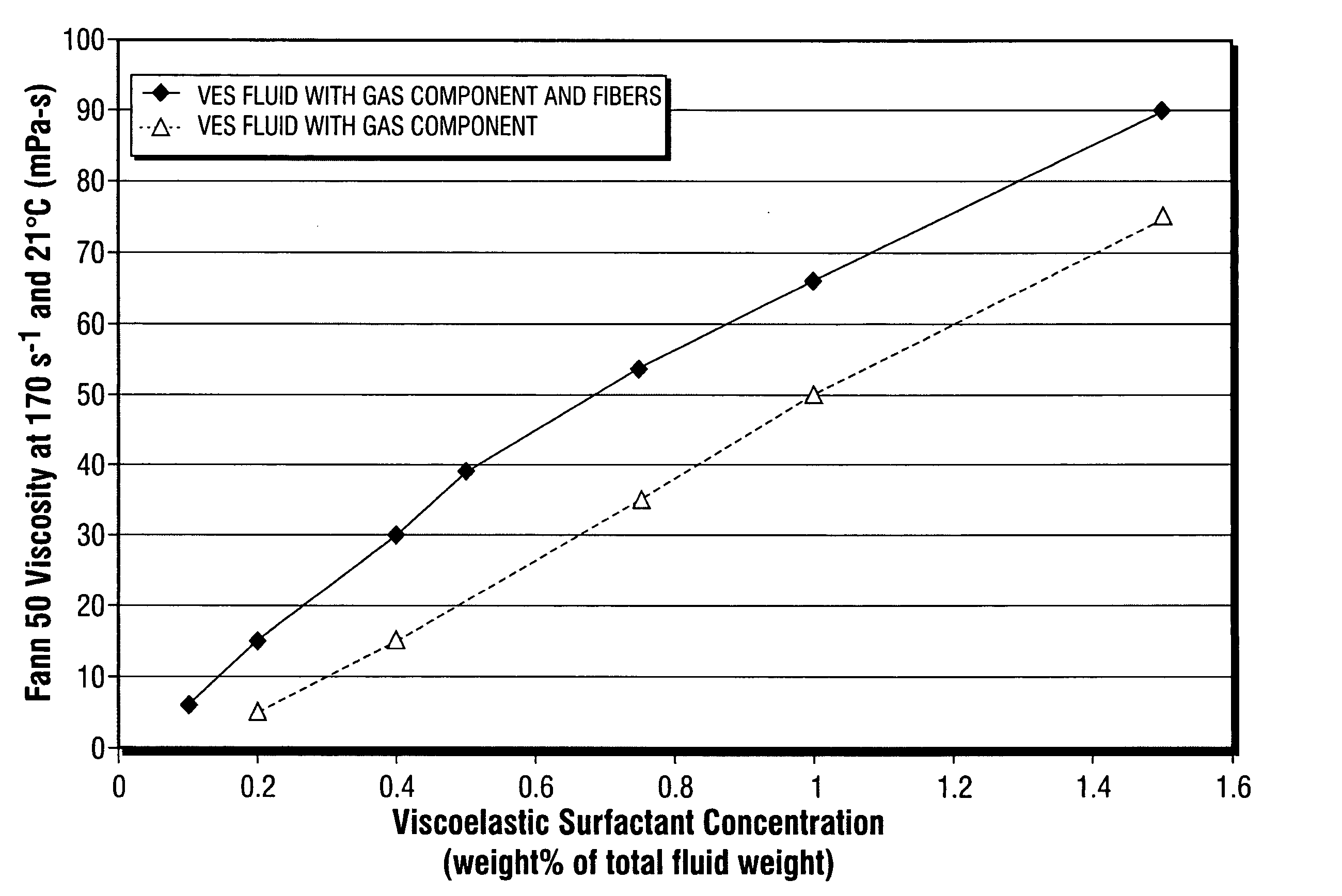
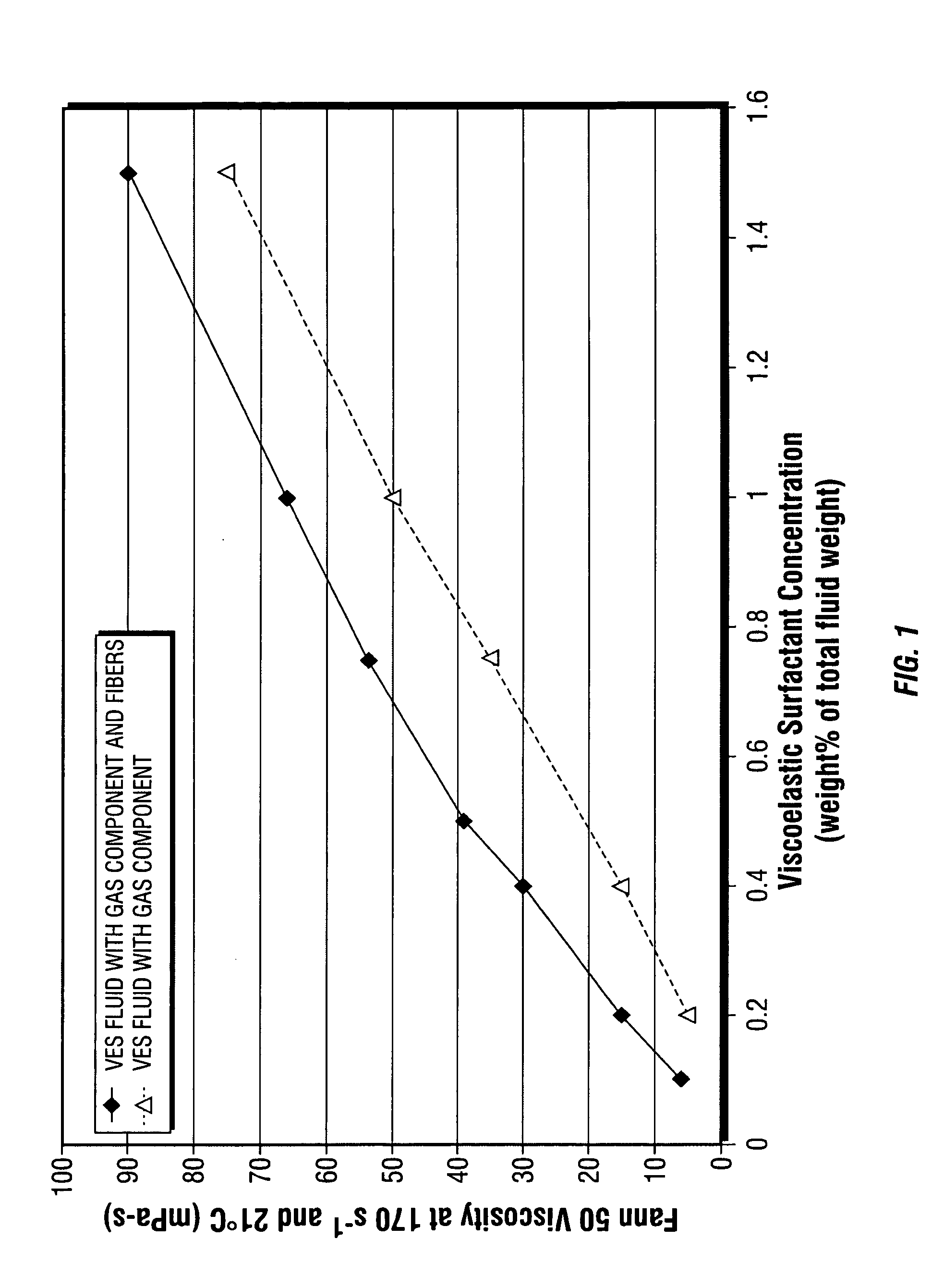
[0044] The following examples, A through L, were prepared individually using a Waring blender. Ingredients added by weight percentage were weighed and added to the blender, and thoroughly mixed. Examples A through G contained fibers. Examples H through L did not contain fibers. 30 quality air was then introduced into the fluid to form a gas component by whipping the fluid / air mixture in the Waring blender. The volumes of gas component and fluid were subsequently measured in a graduated cylinder to determine the volume ratio of gas to fluid. Fann 50 viscosity was measured in each example at 170 s−1 and 21° C.

Examples of VES Fluids Containing Fibers and a Gas Component(% amounts in wt % of total fluid wt %)ExampleExampleExampleExampleExampleExampleExampleABCDEFGWater97.4%97.3% 97.1%97.0%96.75%96.5%96.0%VES fluid 0.1% 0.2% 0.4% 0.5% 0.75% 1.0% 1.5%exampleAmmonium 1.5% 1.5% 1.5% 1.5% 1.5% 1.5% 1.5%Nitrate6.4 mm 1.0% 1.0% 1....

examples m

and N

Proppant Containing VES Fluids

[0046] A benefit of adding fibers to viscoelastic fluids containing a gas component and proppant is significant extension of proppant settling time. To illustrate this benefit, the Examples M and N were prepared and evaluated.

[0047] In a Waring blender, 1% by weight of the viscoelastic surfactant fluid example above was mixed with 1.5% by weight ammonium nitrate and 97.5% by weight water. 30 quality air was then introduced into the fluid to form a gas component by whipping the fluid / air mixture in the Waring blender. The resultant fluid had a measured viscosity of 51 mPa-s at 170 s−1 and 21° C. Sand, as a proppant, was added to the gas containing fluid in the amount of 0.24 kg per liter of fluid, thus generating Example M. The foam half-life (to test gas phase stability) and proppant settling time were evaluated. The foam half-life was determined by the tests as set forth in U.S. Pat. No. 4,108,782, columns 5 and 6, under the headings “Initial Fo...


PUM


Abstract

The present invention relates to aqueous oilfield treatment fluids containing a gas component and fibers, wherein the fluids may further include a viscosifying agent and/or proppant. The fluids have good proppant suspension and transport properties as well as excellent gas phase stability. Use of fluids comprising an aqueous medium, a gas component, viscosifying agent, and fibers for hydraulically fracturing a subterranean formation, cleanup operations, and gravel packing a wellbore, are also disclosed.

Description

BACKGROUND OF THE INVENTION [0001] This invention relates to fluids used in treating a subterranean formation. In particular, the invention is oilfield treatment fluids containing a gas component and fibers, and uses thereof. [0002] Various types of fluids are used in operations related to the development, completion, and production of natural hydrocarbon reservoirs. The operations include fracturing subterranean formations, modifying the permeability of subterranean formations, or sand control. The oilfield stimulation fluids employed in these operations are known as drilling fluids, completion fluids, work over fluids, packer fluids, fracturing fluids, drilling fluids, conformance or permeability control fluids, and the like. [0003] Fluid technologies incorporating a gas component to form a foam or energized fluid are commonly used as oilfield treatment fluids. For example, some viscoelastic fluids used as fracturing fluids contain a gas such as air, nitrogen or carbon dioxide to ...

Claims


Application Information

Patent Timeline
IPC IPC(8): E21B43/26
CPCC09K8/52C09K8/665C09K2208/30C09K8/703C09K2208/08C09K8/68Y10S507/906
Inventor SULLIVAN, PHILIP F.FREDD, CHRISTOPHER N.
Owner SCHLUMBERGER TECH CORP
Why Eureka
Try Eureka