Scanning electron microscope having multiple detectors and a method for multiple detector based imaging

a scanning electron microscope and detector technology, applied in the field of scanning electron microscopes, can solve problems such as inability to provide tilted images, and achieve the effect of high tilt angle and high quality

Active Publication Date: 2006-03-16
APPL MATERIALS ISRAEL LTD
View PDF49 Cites 10 Cited by
  • Summary
  • Abstract
  • Description
  • Claims
  • Application Information

AI Technical Summary

Benefits of technology

[0014] The invention provides a system and method for high-resolution multi-perspective SEM imaging that also provides high quality tilt images, including relatively high tilt angles that involve mechanical tilt.

Problems solved by technology

This SEM has various disadvantages, such as not being capable of providing tilted images.

Method used


Image

  • Scanning electron microscope having multiple detectors and a method for multiple detector based imaging
  • Scanning electron microscope having multiple detectors and a method for multiple detector based imaging
  • Scanning electron microscope having multiple detectors and a method for multiple detector based imaging

Examples


Embodiment Construction

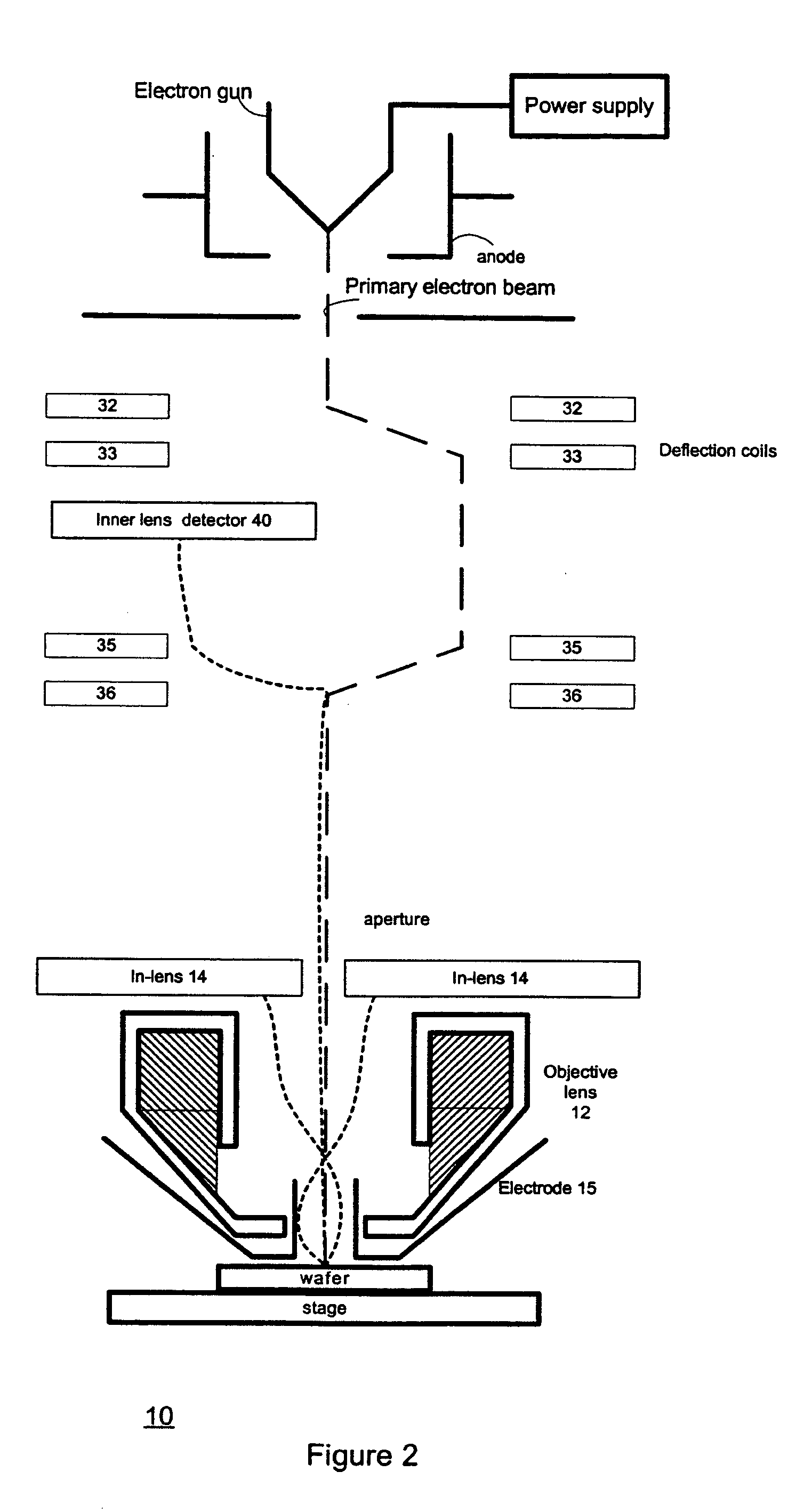
[0026]FIG. 2 is an illustration of a portion of multiple detector SEM in accordance to an embodiment of the invention. FIG. 2 also illustrates an exemplary path of a primary electron beam path, as well as the paths of electrons that are scattered or reflected from an inspected object, such as but not limited to a wafer or a reticle.

[0027] The primary electron beam propagates along an optical axis and is than (i) tilted at a first direction, (ii) tilted at an opposite direction such as to propagate along a secondary optical axis that is parallel to the optical axis but spaced apart from the optical axis, (iii) tilted, at a second direction, towards the optical axis and then (iv) tilted, at a direction opposing the second direction, such as to propagate along the optical axis. The mentioned above tilt operations may be generated by magnetic deflection coils 32-36. A system and method for double tilt is described at patent application Ser. No. 10 / 146,218 filed 13 May 2002, and is inco...


PUM

PropertyMeasurementUnit
diameteraaaaaaaaaa
diameteraaaaaaaaaa
tilt angleaaaaaaaaaa

Abstract

A system and method for multi detector detection of electrons, the method includes the steps of directing a primary electron beam, through a column, to interact with an inspected object, directing, by introducing a substantial electrostatic field, electrons reflected or scattered from the inspected objects towards multiple interior detectors, whereas at least some of the directed electrons are reflected or scattered at small angle in relation to the inspected object; and receiving detection signals from at least one interior detector.

Description

RELATED APPLICATION [0001] This application claims the priority of U.S provisional patent application titled “high resolution multi perspective SEM imaging”, application No. 60 / 491,618, filed 30 Jul. 2003.FIELD OF THE INVENTION [0002] The invention relates to scanning electron microscopes and especially to a multiple-detector SEM and a method for multiple detector based detection. BACKGROUND OF THE INVENTION [0003] A prior art multi perspective scanning microscope (MPSI) system 10 is described in FIG. 1. System 10 includes an electron gun (not shown) for generating a primary electron beam, as well as multiple control and voltage supply units (not shown), an objective lens 12, in-lens detector 14 and external detectors 16. System 10 also includes deflection coils and a processor (not shown). [0004] In system 10 the primary electron beam is directed through an aperture 18 within the in-lens detector 14 to be focused by the objective lens 12 onto an inspected wafer 20. The primary elec...

Claims


Application Information

Patent Timeline
Patent Type & Authority Applications(United States)
IPC IPC(8): G21K7/00G01N23/225H01J37/244H01J37/28
CPCG01N23/2251H01J37/244H01J37/28H01J2237/24465H01J2237/2817H01J2237/2449H01J2237/24495H01J2237/281H01J2237/2815H01J2237/24475H01L22/00
Inventor SHEMESH, DRORADAMEC, PAVEL
Owner APPL MATERIALS ISRAEL LTD
Why Eureka
Try Eureka