
Composite scintillators for detection of ionizing radiation

a technology of ionizing radiation and scintillators, which is applied in the direction of luminescent compositions, material nanotechnology, other chemical processes, etc., can solve the problems of limiting difficult to detect neutrons directly, and the greatest deficiency of scintillators in the field of neutron scintillators, so as to improve the efficiency of neutron detection.

Inactive Publication Date: 2006-03-16
BWXT Y 12 +1
View PDF7 Cites 163 Cited by
  • Summary
  • Abstract
  • Description
  • Claims
  • Application Information

AI Technical Summary

Benefits of technology

[0015] Accordingly, it is an object of the present invention to provide crack-free composite scintillators having enhanced transparency for detecting a wide variety of different kinds of ionizing radiation.
[0016] It is another object of the present invention to provide crack-free composite scintillators having enhanced transparency with high scintillation light emission intensity.
[0017] It is yet another object of the present invention to provide crack-free composite scintillators having enhanced transparency for neutron detection that exhibit low gamma interference (e.g., false neutron counts produced by gamma rays).

Problems solved by technology

At this time, the greatest deficiency in the area of scintillators is in neutron scintillators.
Because neutrons travel through matter in such a manner, neutrons are difficult to detect directly.
The major drawback to composite scintillators is their tendency to be optically opaque, making them useable only in a thin film form, limiting their efficiency for detecting neutrons.
The consequent lack of consistent neutron pulses amplitude, and thus a neutron capture reaction energy peak, makes it very difficult to know where to set specific minimum amplitude for rejection of non-neutron (e.g., gamma) pulses and to know what fraction of gamma and what fraction of neutron pulses are accepted and rejected as a result.
Because of the high temperature employed, these materials are very difficult to integrate as films into electronic devices for neutron detection or to cast as large screens.
Furthermore, the high temperature methods eliminate the possibility of using organic scintillators because such organic compounds are seldom stable at elevated temperatures.
Typically, due to the exotic materials and sensitivity of the equipment, the neutron detectors currently available are expensive and difficult to maintain.
Furthermore, the use of a gas absorber results in a slower response time than a solid absorber as disclosed herein.

Method used


Image

  • Composite scintillators for detection of ionizing radiation
  • Composite scintillators for detection of ionizing radiation
  • Composite scintillators for detection of ionizing radiation

Examples


example 1

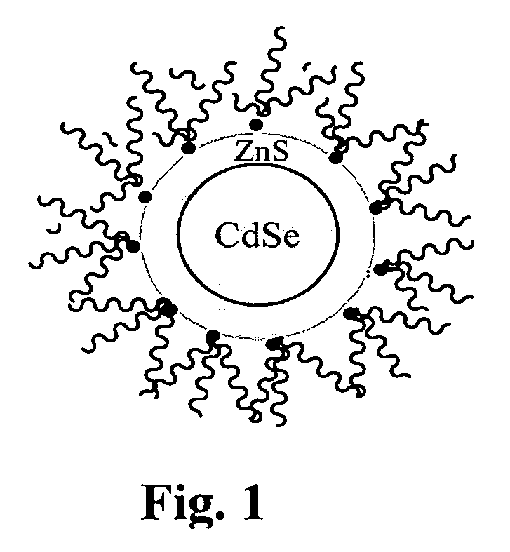
[0077] All syntheses and handling of CdSe / ZnS core / shell nanocrystals were preformed under an inert atmosphere. In a typical synthesis, cadmium acetate (100 mg) was dissolved in tri-n-octylphosphine oxide (6.0 g, TOPO) in a reaction flask. The temperature was then raised to 270° C. Into the reaction flask at 270° C., a solution of selenium (80 mg) in tributylphosphine (2.0 mL, CAUTION: pyrophoric) was swiftly injected. Upon injection of selenium solution, the reaction temperature dropped to around 250° C. The uniform CdSe nuclei were allowed to grow at this temperature (250° C.) for various lengths of time (from 0 to 3 min) to yield various sizes of nanocrystals which photoluminesce at wavelengths ranging from 470 to 550 nm. The reaction was then allowed to cool down to room temperature at which anhydrous methanol was added to precipitate CdSe nanocrystals. The obtained nanocrystals were washed three times with copious amount of fresh, anhydrous methanol. The next step is the cappin...


PUM


Abstract

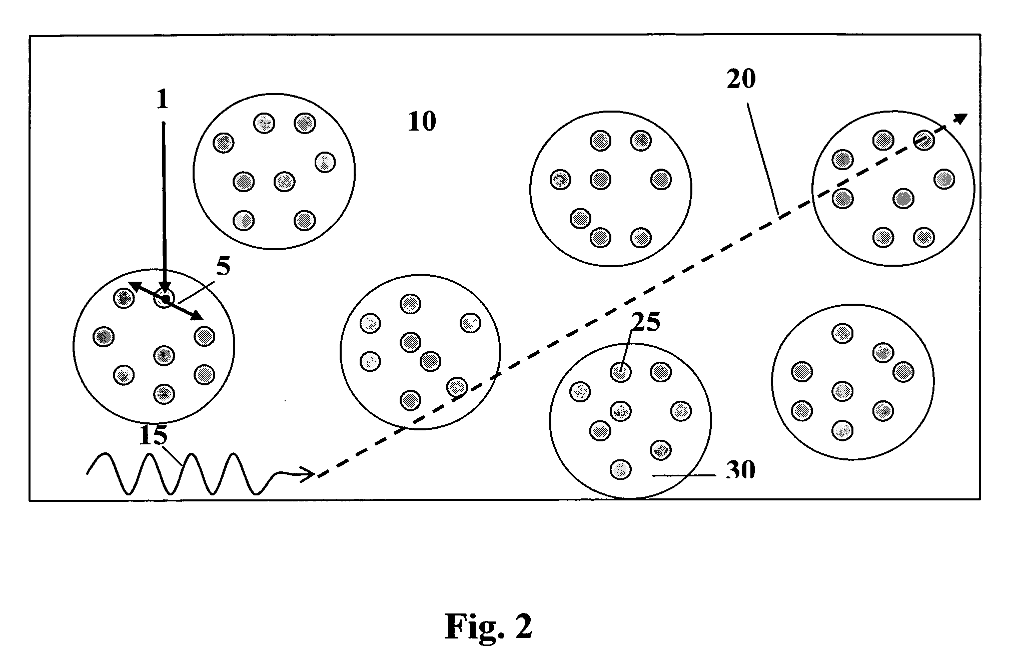
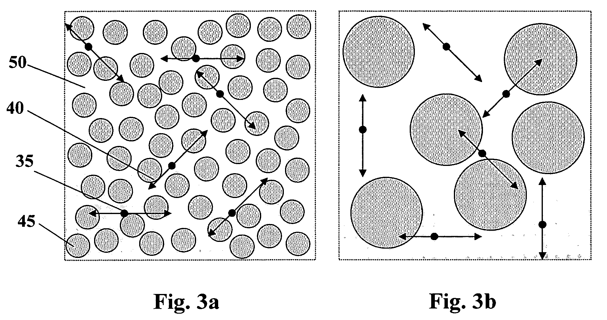
Applicant's present invention is a composite scintillator having enhanced transparency for detecting ionizing radiation comprising a material having optical transparency wherein said material comprises nano-sized objects having a size in at least one dimension that is less than the wavelength of light emitted by the composite scintillator wherein the composite scintillator is designed to have selected properties suitable for a particular application.

Description

[0001] The United States government has rights in this invention pursuant to contract no. DE-AC05-000R22725 between the United States Department of Energy and UT-Battelle, LLC.FIELD OF THE INVENTION [0002] The present invention relates to scintillators for detection of ionizing radiation, and more particularly, to composite scintillators having enhanced transparency comprising transparent material of nano-sized objects having a size in at least one dimension that is less than the wavelength of light emitted by the composite scintillator for detection of a wide variety of ionizing radiation. BACKGROUND OF THE INVENTION [0003] Scintillators, defined as materials that emit light upon absorbing ionizing radiation or energy from ionizing radiation, are one of the primary means for detecting most kinds of radiation. There is a need among the research, defense and industrial communities for scintillators that demonstrate improved capabilities in terms of light output, detection efficiency,...

Claims


Application Information

Patent Timeline
IPC IPC(8): C09K11/77
CPCB82Y10/00B82Y30/00C09K11/02G21K4/00C09K11/565C09K11/883C09K11/06
Inventor DAI, SHENGSTEPHAN, ANDREW CURTISBROWN, SUREE S.WALLACE, STEVEN A.RONDINONE, ADAM J.
Owner BWXT Y 12
Learn More