

Electric power steering apparatus
a technology of electric power steering and electric motor, which is applied in mechanical devices, transportation and packaging, and equipment, etc., can solve the problems of increasing the cost of vehicles, and achieve the effect of reducing the size of the electric power steering apparatus
- Summary
- Abstract
- Description
- Claims
- Application Information
AI Technical Summary
Benefits of technology
Problems solved by technology
Method used
Image

Examples
first embodiment
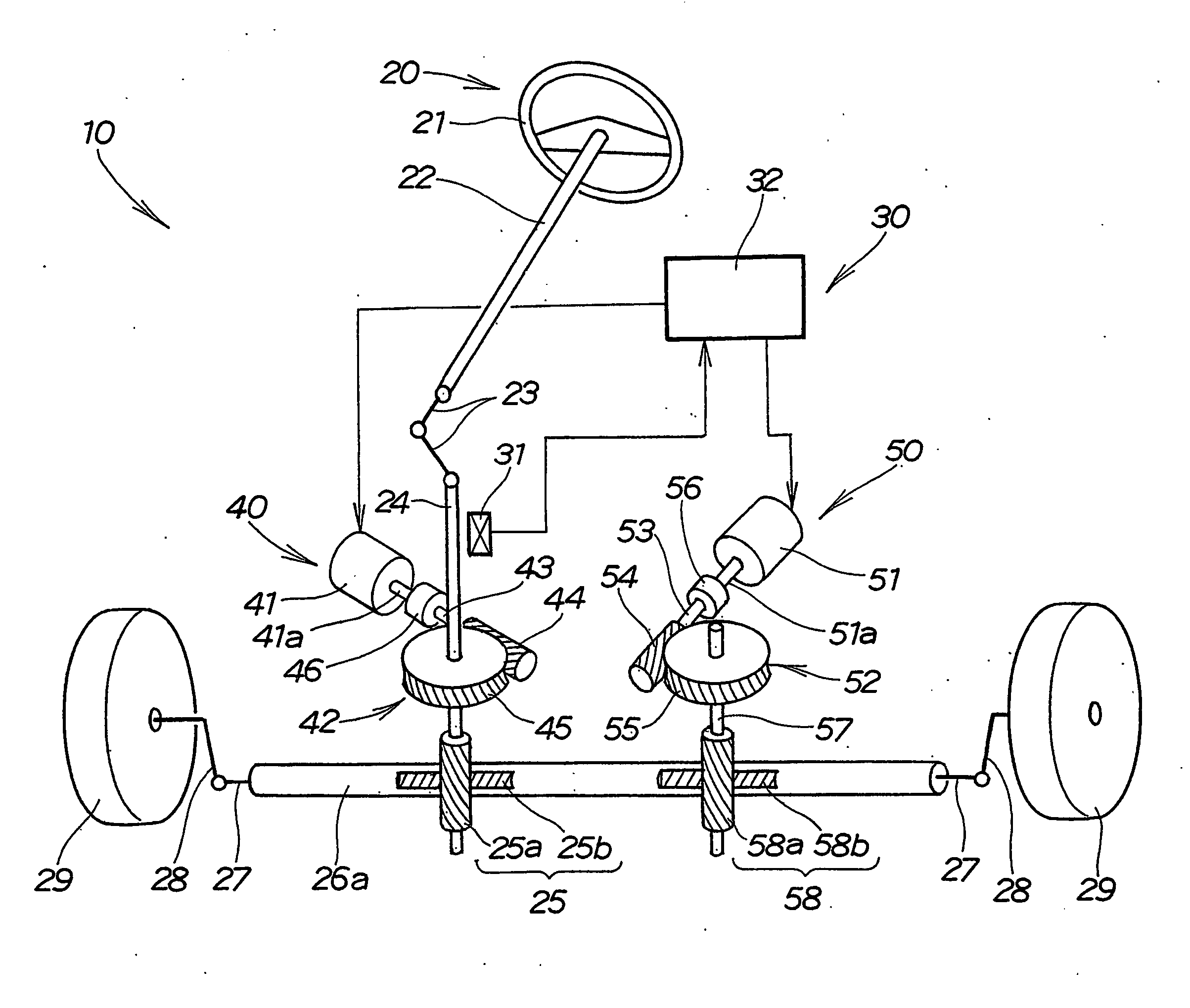
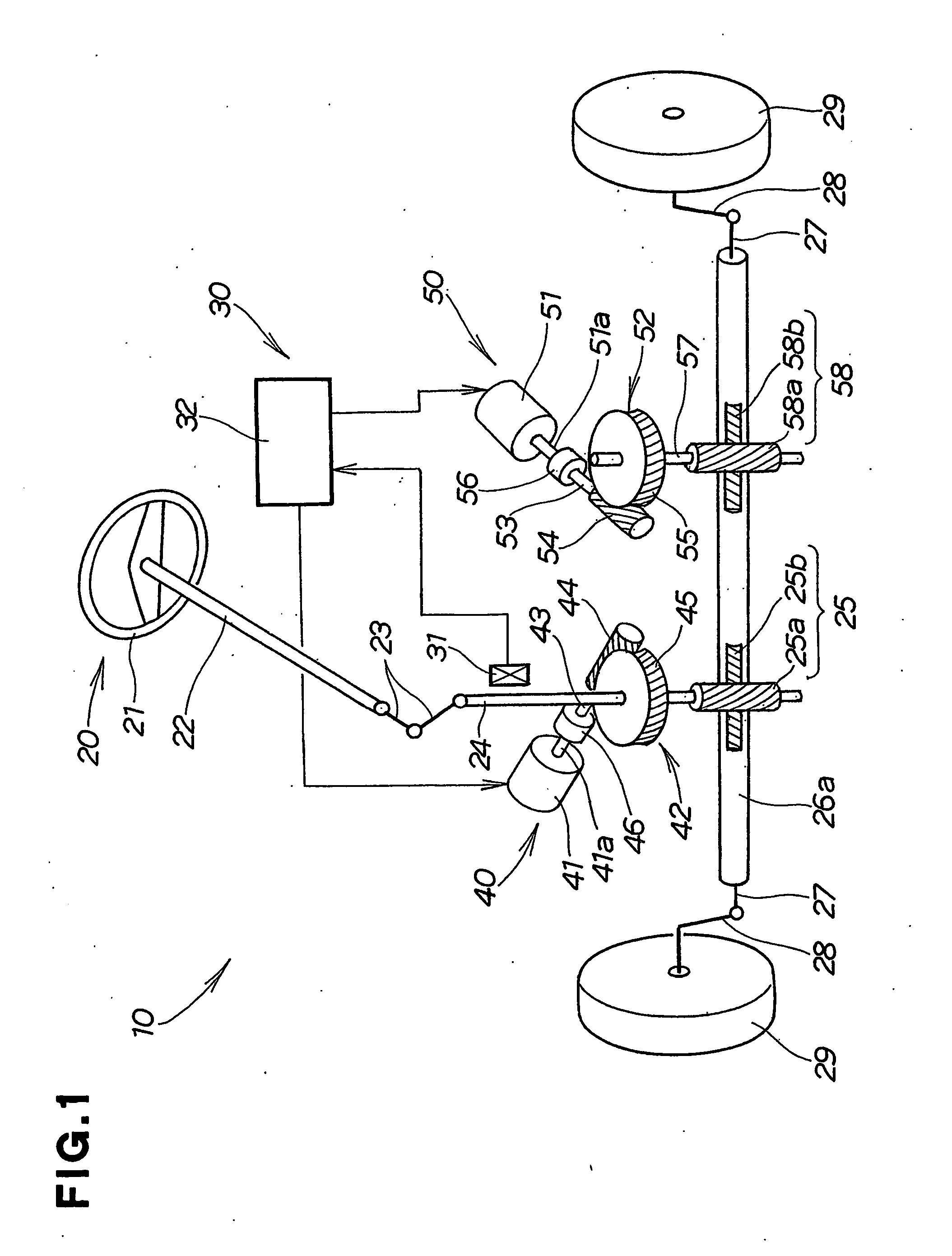
[0044] Referring to FIG. 1 through FIG. 6, there is shown an electric power steering apparatus 10 according to the present invention. The apparatus 10 includes a steering system 20 and an assist torque mechanism 30 for providing an assist torque to the steering system 20.
[0045] As shown in FIG. 1, the steering system 20 includes a steering wheel 21, a steering shaft 22 attached at one end to the steering wheel 21, a universal joint 23 having its one end connected to the other end of the steering shaft 22, a pinion shaft 24 having its one end connected to the other end of the universal joint 23, and a rack shaft 26a connected to the other end of the pinion shaft 24 through a rack-and-pinion mechanism 25. The rack shaft 26a has a right end connected to one end of a right tie rod 27. The rack shaft 26a has a left end connected to one end of a left tie rod 27. The right tie rod 27 is connected via a knuckle 28 to a right vehicle wheel 29. The left tie rod 27 is connected via a knuckle 2...
second embodiment
[0071] Referring to FIG. 7 through FIG. 9, there is shown an electric power steering apparatus 100 according to the present invention. The electric power steering apparatus 100 is the same as the electric power steering apparatus 10 except that the assist torque mechanism 30 includes a third assist torque producing device 150 instead of the second assist torque producing device 50. In FIG. 7 to FIG. 9, the same components of the electric power steering apparatus 100 as those of the electric power steering apparatus 10 are identically numbered and their detail description will be omitted.
[0072] More specifically, the assist torque mechanism 30 of the apparatus 100 includes the steering torque sensor 31, the control section 32, and the first and third assist torque producing devices 40, 150. The third assist torque producing device 150 includes a third electric motor 151 and a ball screw 160 connecting the motor 151 to a rack shaft 26b therethrough.
[0073] As show in FIG. 7, the rack ...
third embodiment
[0085] Referring to FIG. 10 through FIG. 13, there is shown an electric power steering apparatus 200 according to the present invention.
[0086] As shown in FIG. 10, the electric power steering apparatus 200 is the same as the electric power steering apparatus 100 except that the assist torque mechanism 30 includes a fourth assist torque producing device 240 instead of the first assist torque producing device 40. The fourth assist torque producing device 240 includes the first electric motor 41 disposed in such a position to provide a motive power to the steering shaft 22. In FIG. 10 to FIG. 13, the same components of the electric power steering apparatus 200 as those of the electric power steering apparatus 100 are identically numbered and their detail descriptions will be omitted.
[0087] The fourth assist torque producing device 240 includes the first electric motor 41 and the first worm gear mechanism 42 for transmitting to the steering shaft 22 the assist torque produced by the fi...
PUM
 Abstract
Description
Claims
Application Information