Stator of motor and method of manufacturing the same

a technology of stator and motor, which is applied in the direction of dynamo-electric machines, electrical apparatus, magnetic circuit shapes/forms/construction, etc., can solve the problems of increased manufacturing costs of stator, limited motor efficiency, and inability to easily and conveniently perform coil winding operation, so as to reduce the manufacturing cost of stator of motor

Inactive Publication Date: 2006-03-16
LG ELECTRONICS INC
View PDF13 Cites 46 Cited by
  • Summary
  • Abstract
  • Description
  • Claims
  • Application Information

AI Technical Summary

Benefits of technology

[0014] Therefore, the present invention has been made in view of the above problems, and it is an object of the present invention to provide a stator of a motor that is capable of being easily manufactured, thereby reducing the manufacturing costs of the stator and improving efficiency of the motor.
[0035] According to the present invention, an electrical steel sheet is bent to prepare a core sheet, and a plurality of core sheets are stacked to prepare a unit core having a predetermined thickness. Consequently, no scrap is formed from the electrical steel sheet, and therefore, the present invention has the effect of reducing the manufacturing costs of the stator of the motor.

Problems solved by technology

Consequently, a large portion of the electrical steel sheet 30 is wasted, and therefore, the manufacturing costs of the stator are increased.
As a result, core loss is large, and therefore, efficiency of the motor is limited.
As a result, the slot 14, which is a coil-winding space, is very small, and therefore, the coil-winding operation is not easily and conveniently performed.
As a result, copper loss is large, and therefore, efficiency of the motor is limited.

Method used


Image

  • Stator of motor and method of manufacturing the same
  • Stator of motor and method of manufacturing the same
  • Stator of motor and method of manufacturing the same

Examples


Embodiment Construction

[0044] Now, preferred embodiments of the present invention will be described in detail with reference to the accompanying drawings.

[0045] It should be understood that stators of motors and methods of manufacturing the same according to numerous preferred embodiments of the present invention may be proposed, although only the most preferred embodiments of the present invention will be described hereinafter. It should also be understood that a detailed description will not be given of the stator of the motor and the method of manufacturing the same according to the present invention identical in construction and operation to the conventional stator of the motor and the conventional method of manufacturing the same.

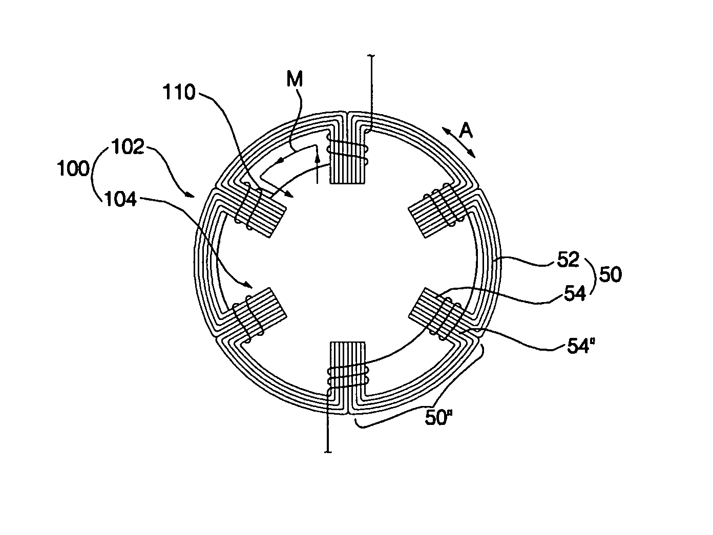
[0046]FIG. 3 is a schematic view illustrating the structure of a stator of a motor according to a preferred embodiment of the present invention, FIG. 4 is a perspective view illustrating a unit core constituting the stator of the motor according to the preferred embodiment...


PUM


Abstract

A method of manufacturing a stator of a motor comprises the steps of bending at least one end of an electrical steel sheet to prepare a core sheet comprising a yoke part and at least one pole part bent from the yoke part, stacking a plurality of core sheets to prepare a unit core having a predetermined thickness, arranging a plurality of unit cores in line to prepare a core band, winding coils on the core band, and connecting both ends of the core band. In this way, the stator is manufactured. Consequently, no scrap is formed from the electrical steel sheet according to the present invention.

Description

BACKGROUND OF THE INVENTION [0001] 1. Field of the Invention [0002] The present invention relates to a stator of a motor and a method of manufacturing the same, and, more particularly, to a stator of a motor, which has a core assembly comprising a plurality of individual unit cores arranged in the circumferential direction of the stator, each unit core being made of an electrical steel sheet having at least one bent end, and a method of manufacturing the same. [0003] 2. Description of the Related Art [0004]FIG. 1 is a schematic view illustrating the structure of a conventional single-phase switched reluctance motor. [0005] As shown in FIG. 1, the conventional single-phase switched reluctance motor comprises: a stator 10 connected to an external power supply; and a rotor 20 rotatably disposed in the stator 10, the rotor 20 performing rotating movement through electro-magnetic interaction between the rotor 20 and the stator 10 when electric current is supplied to the stator 10 from th...

Claims


Application Information

Patent Timeline
Patent Type & Authority Applications(United States)
IPC IPC(8): H02K3/00H02K1/00
CPCH02K15/02H02K1/14H02K1/185H02K3/522
Inventor KIM, BYUNG TAEK
Owner LG ELECTRONICS INC
Why Eureka
Try Eureka