Method and apparatus for carrying out a mox fuel rod quality control

a technology of mox fuel rod and quality control equipment, which is applied in the direction of nuclear monitoring, climate sustainability, nuclear energy generation, etc., can solve the problems of additional challenge for quality control equipment, failure of cladding, irreversible degradation of the isotopic composition of plutonium,

a technology of mox fuel rod and quality control equipment, which is applied in the direction of nuclear monitoring, climate sustainability, nuclear energy generation, etc., can solve the problems of additional challenge for quality control equipment, failure of cladding, irreversible degradation of the isotopic composition of plutonium,

US20060056566A1Inactive Publication Date: 2006-03-16BELGONUCLEAIRE SA

Image

  • Method and apparatus for carrying out a mox fuel rod quality control
  • Method and apparatus for carrying out a mox fuel rod quality control
  • Method and apparatus for carrying out a mox fuel rod quality control

Examples


examples of embodiments

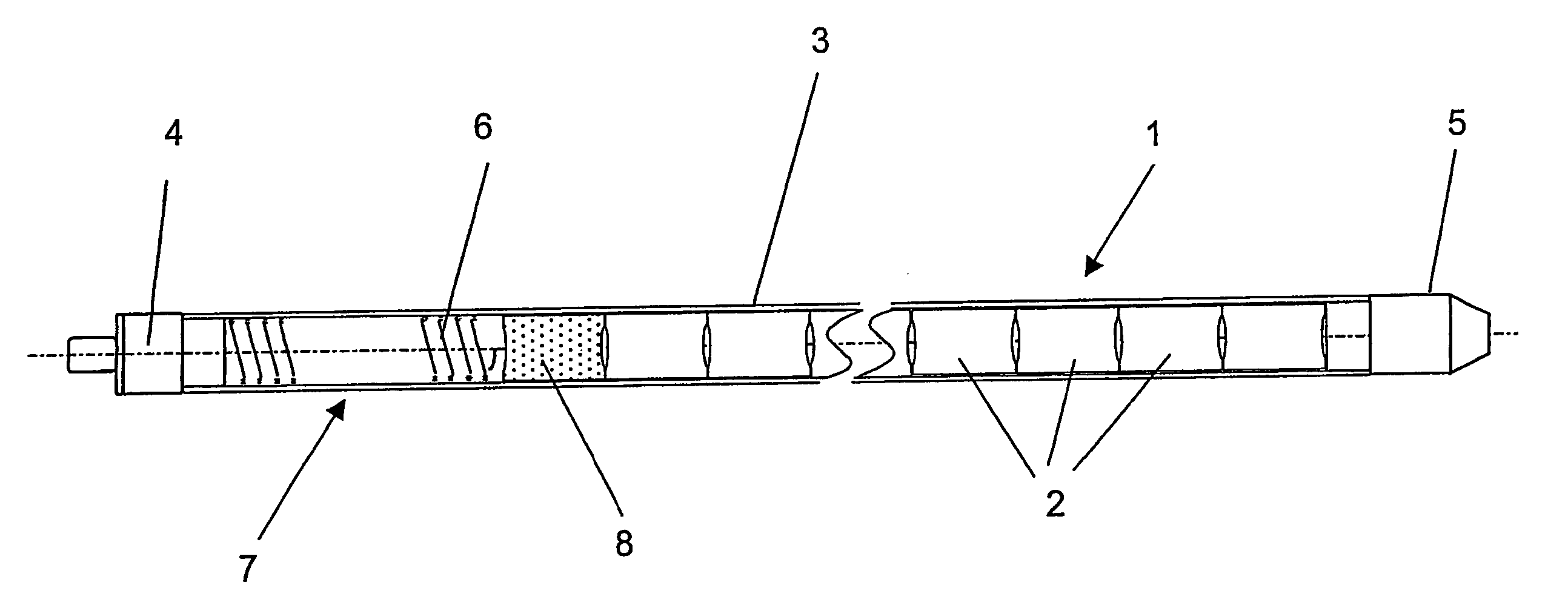
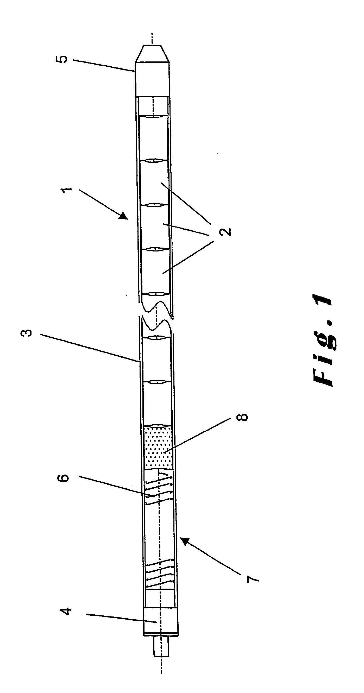
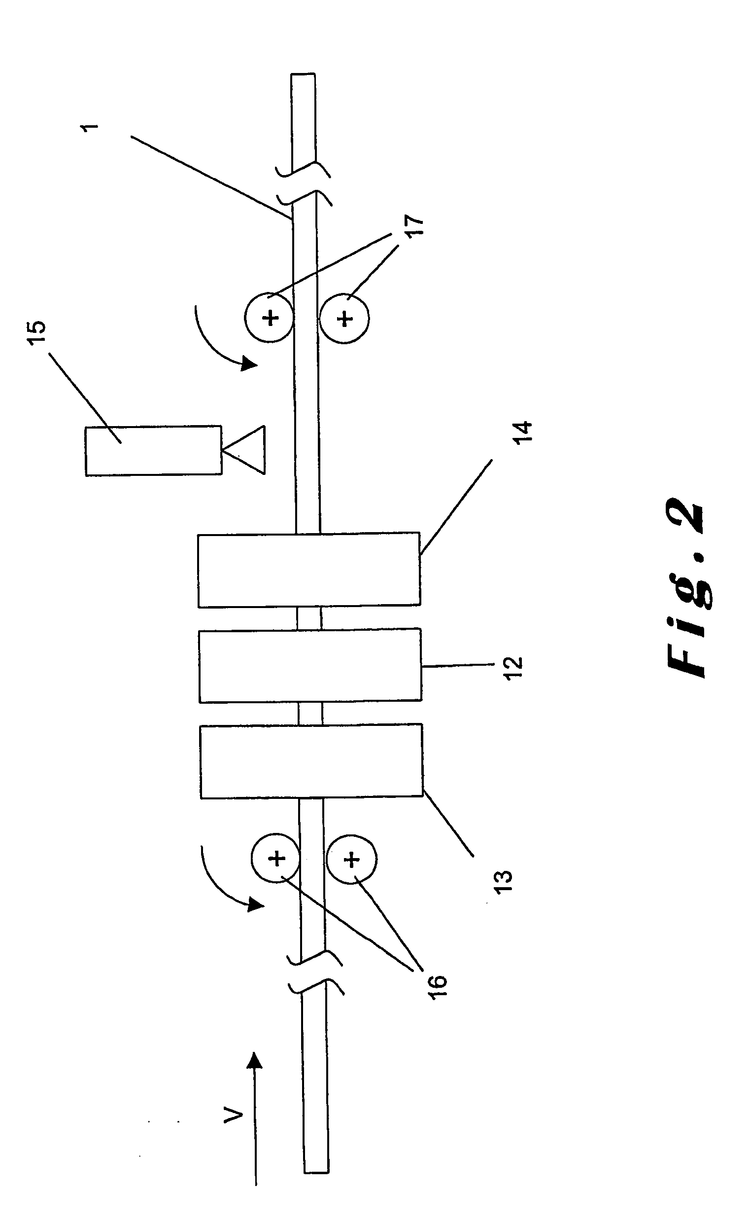
[0083] Non-limiting examples of individual devices used and of an apparatus implementing the integrated quality control method are provided hereunder for illustration of the method.

[0084] The constant speed movement V of the fuel rods 1 in front of the controlling devices 12-15 can be obtained by a driving mechanism with the pressing rolls 16, 17 driven by two stepping motors strictly electronically synchronized, one located at the feed end of the apparatus and the other at the exit end.

[0085] The rods 1 are loaded from a load table and unloaded to an unload table, with mono-layers of rods, thereby providing self-shielding of the controlling devices.

[0086] To enhance the counting of the native γ-emission in order to have the appropriate precision, an annular geometry for the NaI (or CdTe) detector 21 is often preferred to an asymmetrical geometry for the embodiment of the invention. For the same purpose, a plurality of photomultipliers 20 fixed to the annular NaI (or CdTe) detect...


PUM


Abstract

A method for carrying out a comprehensive quality control of MOX fuel rods, including measurement of plutonium content of pellets contained in the rod, check of internal structure and constituents in the rod, including the detection of rogue pellets, and measurement of dimensional characteristics and radioactive contamination along the rod surface, by moving the fuel rod axially, performing concurrently the measurements and checks along the fuel rod moved axially, using radiometry and radiography. An apparatus for carrying out the method.

Description

[0001] This invention relates to a method for a comprehensive quality control of MOX (mixed oxide) fuel rods, and to an apparatus designed for carrying out said method. BACKGROUND OF THE INVENTION [0002] Nuclear fuel rods are utilized in most power reactors (light water reactors, heavy water reactors, breeder reactors, . . . ) as the elementary unit isolating the nuclear fuel from the environment. As such, they must meet high quality standards and are controlled accordingly, before being released for mounting into a fuel assembly (sometimes called fuel element or fuel bundle), which is the final product, used to transport the fuel, to load it into the reactor, to maintain it in the reactor core, to unload it from the reactor and eventually to dispose of it by interim storage for later reprocessing or final disposal. [0003] A fuel rod 1 (FIG. 1) consists typically of a stack of pellets 2 made from fissionable material, enclosed in a tube or cladding 3, sealed at both open ends by an ...

Claims


Application Information

Patent Timeline
16 Mar 2006
Publication
US20060056566A1
IPC
G21C17/00; G21C17/06
CPC
G21C17/06; G21Y2002/202; G21Y2002/204; G21Y2004/40; G21Y2002/501; G21Y2004/30; G21Y2002/304; Y02E30/30
Inventors
VANDERGHEYNST, ALAIN; EECKHOUT, FRANCOIS