User interface for an image transformation device

a technology of image transformation and user interface, which is applied in the direction of digital data processing details, computer security arrangements, digital recording carriers, etc., can solve the problems that cameras produced today are unable to take advantage of technologies not yet available, and filters are not able to be used. , to achieve the effect of facilitating image processing, the form of image processing is easily adaptabl

Inactive Publication Date: 2006-03-16
SILVERBROOK RES PTY LTD
View PDF2 Cites 129 Cited by
  • Summary
  • Abstract
  • Description
  • Claims
  • Application Information

AI Technical Summary

Benefits of technology

[0010] It is an object of the present invention to provide a system which readily is able to take advantage of updated technologies in a addition to taking advantage of new filters being created and, in addition, providing a readily adaptable form of image processing of digitally captured images for printing out.

Problems solved by technology

Unfortunately, changing digital imaging technologies and changing filter technologies result in onerous system requirements in that cameras produced today obviously are unable to take advantages of technologies not yet available nor are they able to take advantage of filters which have not, as yet, been created or conceived.

Method used


Image

  • User interface for an image transformation device
  • User interface for an image transformation device
  • User interface for an image transformation device

Examples


case 2

[0668] No special processing is recorded except for setting the ‘PrevCaseWasCase2’ flag for identifying Case 3 (see Step 3 of processing a column described above)

[0669] Case 3:

PrevCaseWasCase2 = TRUEIf (WhiteDetectCount[Target]BlackDetectCount[Target]>= 8TargetRow[Target] = S2StartPixel + (S2RunLength / 2)WhiteDetectCount=1EndIfΔ := ABS(S2StartPixel − PrevColStartPixel[Target])If (0WhiteDetectCount[Target]++ElseWhiteDetectCount[Target] := 1EndIfPrevColStartPixel[Target] := S2StartPixelThisColumnDetected := TRUEBitDetected = 0

[0670] At the end of processing a given column, a comparison is made of the current column to the maximum number of columns for target detection. If the number of columns allowed has been exceeded, then it is necessary to check how many targets have been found. If fewer than 8 have been found, the card is considered invalid.

Process Targets

[0671] After the targets have been detected, they should be processed. All the targets may be available or merely some of...

example 1

[1953] Suppose we have a car with associated car-keys. A 16-bit key number is more than enough to uniquely identify each car-key for a given car. The 256 bits of M could be divided up as follows:

M[n]AccessDescription0ROKey number (16 bits)1-4ROCar engine number (64 bits)5-8ROFor future expansion = 0 (64 bits) 8-15RORandom bit data (128 bits)

[1954] If the car manufacturer keeps all logical keys for all cars, it is a trivial matter to manufacture a new physical car-key for a given car should one be lost. The new car-key would contain a new Key Number in M[0], but have the same K1 and K2 as the car's Authentication Chip. Car Systems could allow specific key numbers to be invalidated (for example if a key is lost). Such a system might require Key 0 (the master key) to be inserted first, then all valid keys, then Key 0 again. Only those valid keys would now work with the car. In the worst case, for example if all car-keys are lost, then a new set of logical keys could be generated for ...

example 2

[1955] Suppose we have a photocopier image unit which should be replaced every 100,000 copies. 32 bits are required to store the number of pages remaining. The 256 bits of M could be divided up as follows:

M[n]AccessDescription0ROSerial number (16 bits)1ROBatch number (16 bits)2MSRPage Count Remaining (32 bits, hi / lo)3NMSR4-7 ROFor future expansion = 0 (64 bits)8-15RORandom bit data (128 bits)

[1956] If a lower quality image unit is made that must be replaced after only 10,000 copies, the 32-bit page count can still be used for compatibility with existing photocopiers. This allows several consumable types to be used with the same system.


PUM


Abstract

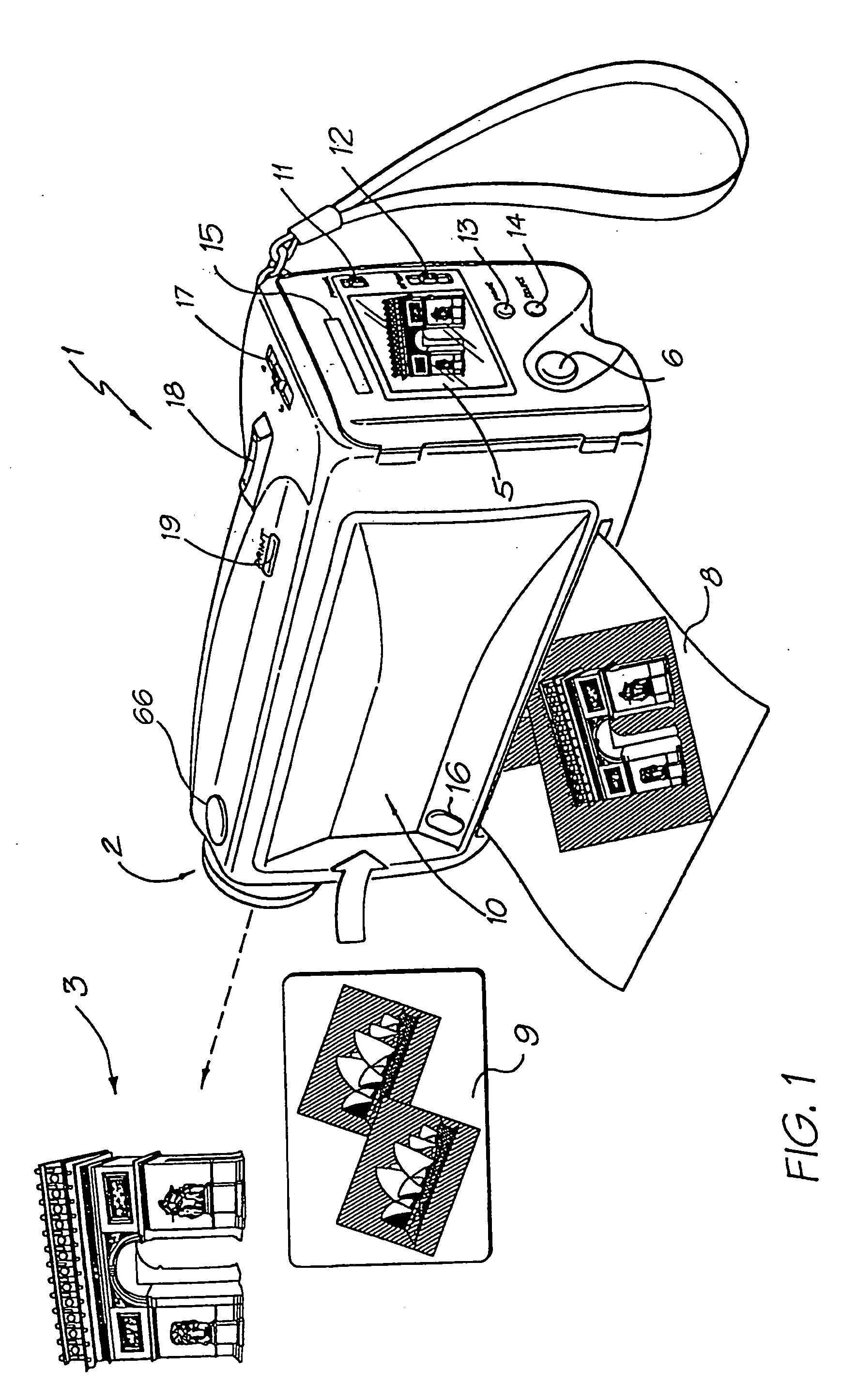
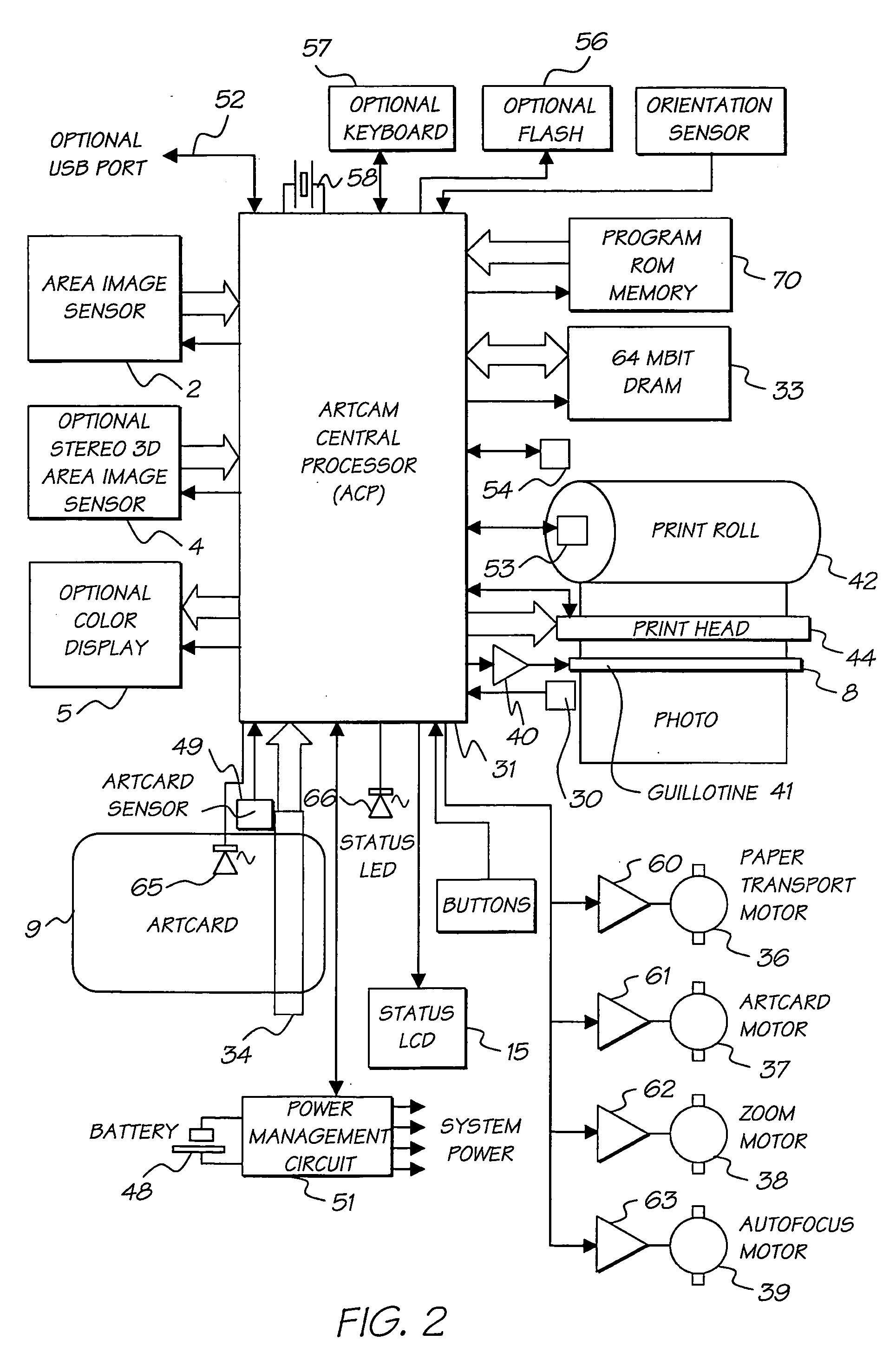
This patent describes an alternative form of user interface for operating a device such as a camera comprising a card which is inserted in a machine. On the face of the card is contained a visual representation of the effect the card will have on the output of the machine. Preferably the camera device is capable of transforming a sensed image substantially in accordance with the transformation of a standard image comprising the visual representation and the transformation of the sensed image is printed out on the printer. Alternatively the machine comprises a book reader and the card includes a books contents for display by the book reader as indicated by the visual representation on the front of the card. On one surface of the card, the visual representation of the effect is displayed, and on a second surface, an optically encoded representation of the effect able to be read by a sensing device of the machine and decoded so as to produce the effect.

Description

CROSS REFERENCE TO RELATED APPLICATIONS [0001] The present application is a continuation of U.S. application Ser. No. 09 / 113,071 filed on Jul. 10, 1998 the entire contents of which are herein incorporated by reference. CROSS REFERENCES TO RELATED APPLICATIONS [0002] The following Australian provisional patent applications are hereby incorporated by reference. For the purposes of location and identification, U.S. patents / patent applications identified by their U.S. patent / patent application Ser. Nos. are listed alongside the Australian applications from which the U.S. patents / patent applications claim the right of priority. US PATENT / CROSS-REFERENCEDPATENT APPLICATIONAUSTRALIAN(CLAIMING RIGHTPROVISIONALOF PRIORITYPATENTFROM AUSTRALIANDOCKETAPPLICATION NO.PROVISIONAL APPLICATION)NO.PO79916,750,901ART01PO85056,476,863ART02PO79886,788,336ART03PO93956,322,181ART04PO80176,597,817ART06PO80146,227,648ART07PO80256,727,948ART08PO80326,690,419ART09PO79996,727,951ART10PO799809 / 112,742ART11PO80...

Claims


Application Information

Patent Timeline
Patent Type & Authority Applications(United States)
IPC IPC(8): G06K9/36B41J2/14B41J2/16B41J2/165B41J2/175B41J3/42B41J3/44B41J11/00B41J11/70B41J15/04B42D15/10G06F1/16G06F21/00G06K1/12G06K7/14G06K19/06G06K19/073G07F7/08G07F7/12G11C11/56H04N1/00H04N1/21H04N1/32H04N5/225H04N5/262
CPCB41J2/14B41J2/14427H01L2924/0002B41J2/16585B41J2/17503B41J2/17513B41J2/17596B41J3/445B41J11/0005B41J11/70B41J15/04B41J2002/041B41J2202/21G03B17/53G06F21/79G06F21/86G06F2221/2129G06K1/121G06K7/14G06K7/1417G06K19/06037G06K19/073G07F7/08G07F7/086G07F7/12G11C11/56H01L23/576H04N1/00127H04N1/00326H04N1/0044H04N1/00965H04N1/2112H04N1/2154H04N1/32133H04N5/225H04N5/2628H04N2101/00H04N2201/3222H04N2201/3269H04N2201/3276H04N2201/328H01L2924/00H04N23/00H04N5/262G06K7/10G03B27/42
Inventor SILVERBROOK, KIALAPSTUN, PAUL
Owner SILVERBROOK RES PTY LTD
Why Eureka
Try Eureka