
Fan speed control circuit

a technology of speed control circuit and fan motor, which is applied in the direction of motor/generator/converter stopper, electronic commutator, dynamo-electric converter control, etc., can solve the problems of high output ripple, vibration, noise in the speed control range, and inability to precisely position the rotor, so as to reduce or even eliminate the electric noise

Active Publication Date: 2006-03-16
DELTA ELECTRONICS INC
View PDF34 Cites 17 Cited by
  • Summary
  • Abstract
  • Description
  • Claims
  • Application Information

AI Technical Summary

Benefits of technology

[0013] An object of the invention is to provide a phase control method of a PWM fan speed control circuit for effectively reducing vibrations and noises in a fan motor.
[0015] Through the design of the invention, since the PWM control signal can be delayed or advanced by a phase angle, the off-time of the PWM control signal can be set to synchronize with the acting period of the back electromotive force formed by the magnetic flux variation. Thus, the abrupt changes of the current waveform are cut off to smooth the rotation of the rotor, and vibrations and noises in the fan motor are considerably reduced as a result.
[0017] By providing the motor and the driver with different powers, the driver is not affected by the first power even though the first power is a pulse power signal thereby reducing or even eliminating the electric noise. Therefore, the design of the motor driving apparatus according to the present invention is novel and unobvious.

Problems solved by technology

In a brushless DC motor, cogging torque is produced by the magnetic attraction between the rotor mounted on permanent magnets and the stator, and it is an undesired effect that makes precise positioning of the rotor impossible because the rotor tends to lock onto the position where it is aligned with the stator poles.
Further, when the rotor rotates, the magnetic flux variation causes back electromotive force (back emf) effect, and the back emf effect in turn enhances the cogging torque to result in high values of output ripple, vibrations, and noises in the fan motor.
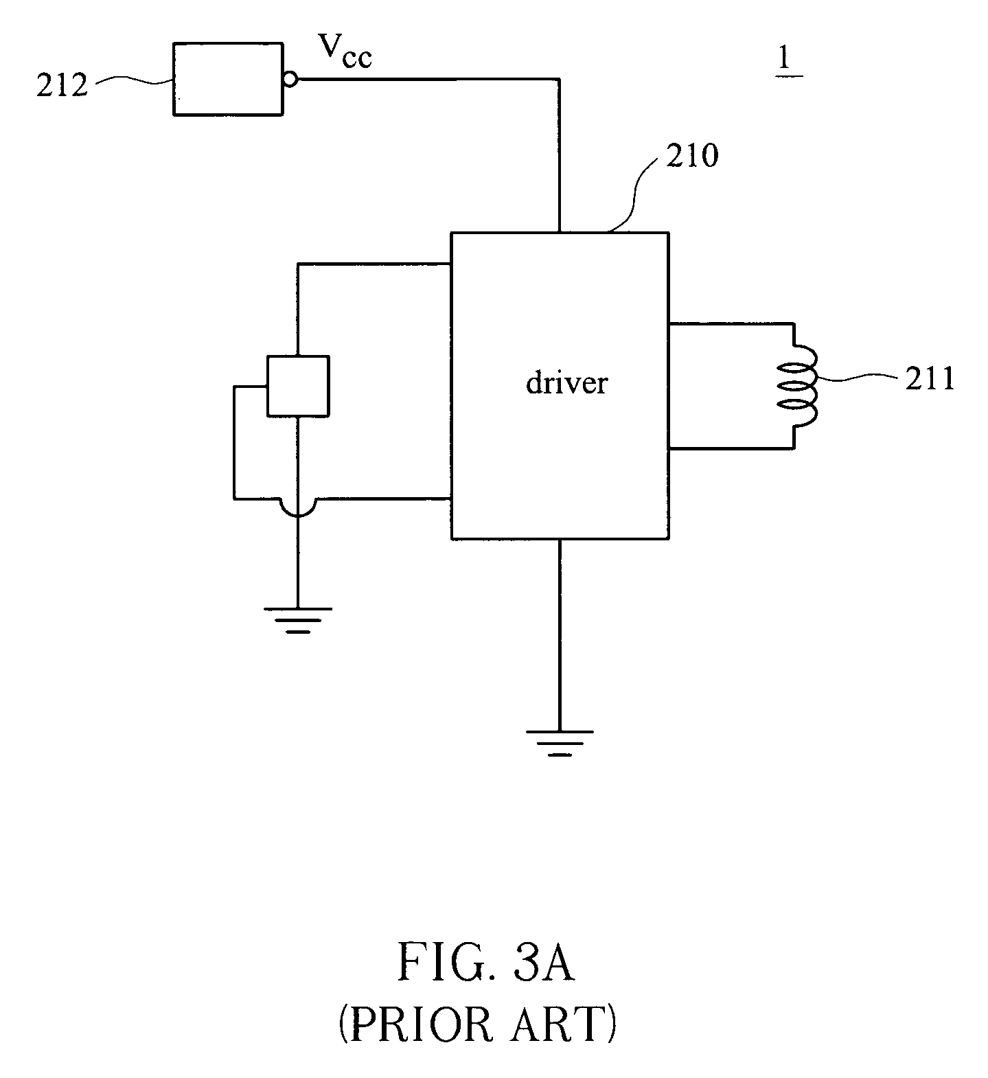
However, such kind of speed control technique is limited by the working voltage of the driver 210 thereby resulting in a narrow speed-control range, and therefore cannot satisfy the industry requirement, gradually.
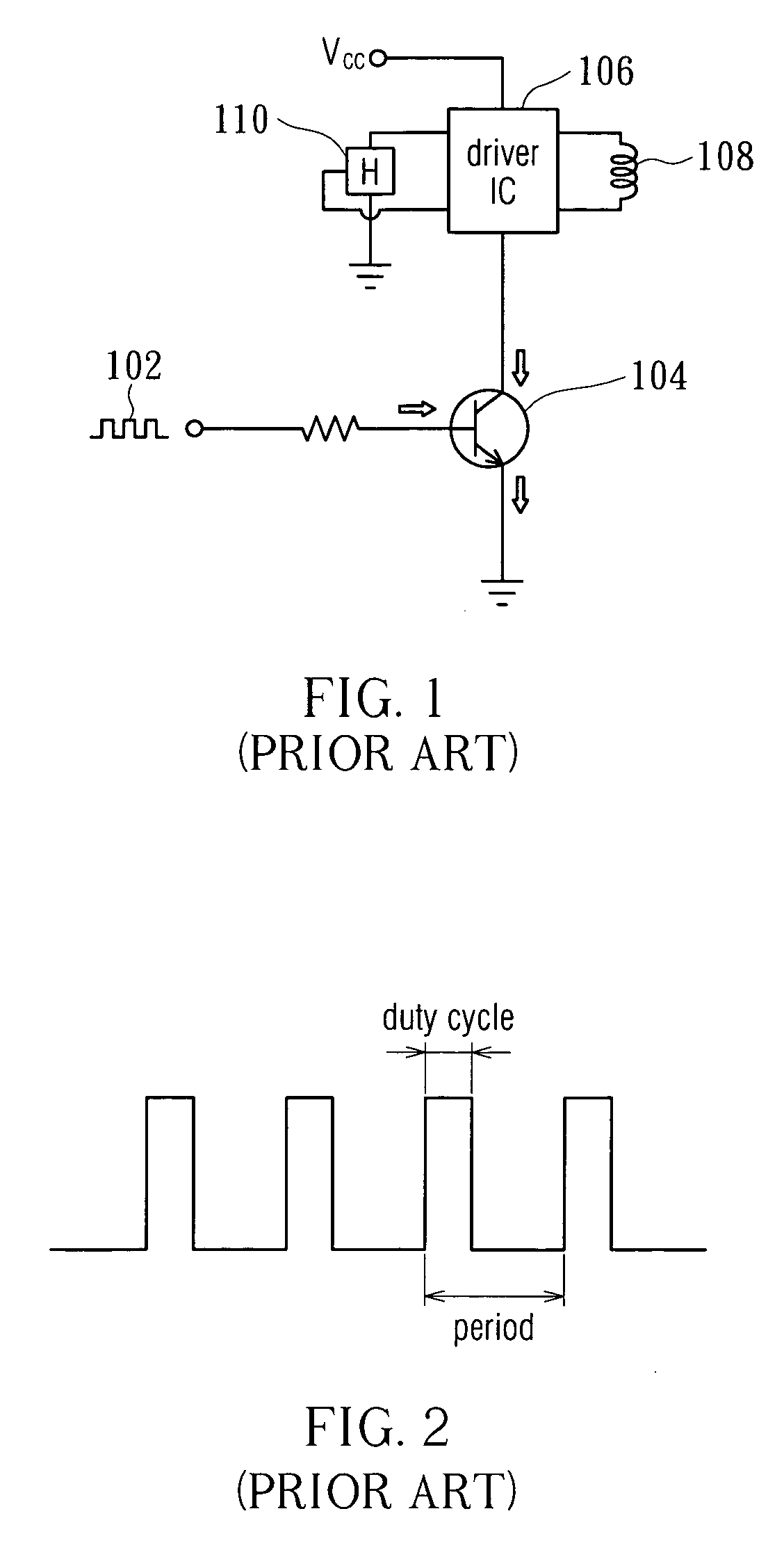
However, the driver (not shown) in the fan motor 220 also performs switching action while the ON / OFF action is performed, thereby producing on / off switching noise which in turn causes electric noise.
Therefore, it is not a good design and needs to be improved.

Method used


Image

  • Fan speed control circuit
  • Fan speed control circuit
  • Fan speed control circuit

Examples


Embodiment Construction

[0033]FIG. 5A is a schematic diagram illustrating the angular position of the rotor 12 relative to the stator 10 in a four-pole DC motor; FIG. 5B illustrates the current waveform of the four-pole DC motor shown in FIG. 5A during unloaded operations, wherein the horizontal axis shows the clockwise-rotating angle (angular position θ) of the rotor 12.

[0034] Comparing the relative angular position of the stator 10 and the rotor 12 in FIG. 5A with the current waveform in FIG. 5B, it can be seen that, for a four-pole motor, the current waveform abruptly changes due to the cogging torque when the rotor 12 rotates to angular positions near nπ / 2 (n=1, 2, 3 . . . ). For instance, after the rotor 12 starts to rotate clockwise from point A, the current waveform abruptly changes when the rotor 12 rotates to an angular position between θ1 (point A′) and π / 2 (point B), and the same is true with each of the other π / 2 periods. On the other hand, since the rotor 12 is divided into four magnetic regi...


PUM


Abstract

A fan speed control circuit includes a pulse width modulation (PWM) signal generating circuit, a driving circuit and a phase compensation unit. The PWM signal generating circuit generates a PWM control signal with a sequence of alternating on-time and off-time, and the driving circuit outputs a driving signal according to the PWM control signal to a fan motor. The phase compensation unit is connected to the fan motor for delaying or advancing the PWM control signal by a phase angle to synchronize the acting period of the back electromotive force formed by the magnetic flux variation with the off-time of the PWM control signal. The present invention further provides a bi-power motor driving system including a motor rotating by receiving a first power from a first power generator, and a driving circuit for driving the motor according to a second power from a second power generator.

Description

CROSS-REFERENCE TO RELATED APPLICATIONS [0001] This application is a continuation-in-part of U.S. application Ser. No. 10 / 839,818 filed May 6, 2004, which claims priority to Taiwan application Serial Number 92118358 filed Jul. 4, 2003, currently pending. The present application is also based on, and claims priority from Taiwan Application Serial Number 94127413 filed Aug. 12, 2005. All of these applications are incorporated herein by this reference.BACKGROUND OF THE INVENTION [0002] (a) Field of the Invention [0003] The present invention relates to a fan speed control circuit and, more particularly, to a fan speed control circuit capable of reducing vibrations and noises in a fan motor by using a phase control method. [0004] (b) Description of the Related Art [0005] Among conventional fan speed control technologies, pulse width modulation (PWM) control is the most common method used to control the speed of direct current (DC) motors. [0006] Referring to FIG. 1, in a conventional PWM...

Claims


Application Information

Patent Timeline
Patent Type & Authority Applications(United States)
IPC IPC(8): H02P7/29
CPCH02P6/142H02P6/15
Inventor WU, CHIA-FENGHUANG, YUEH-LUNGTSAI, MING-SHIHUANG, WEN-SHI
Owner DELTA ELECTRONICS INC
Learn More