Compressor and driving motor assembly

Inactive Publication Date: 2006-03-16
INGERSOLL RAND SERVICES LTD
View PDF33 Cites 13 Cited by
  • Summary
  • Abstract
  • Description
  • Claims
  • Application Information

AI Technical Summary

Benefits of technology

[0021] The preferred assembly is small, compac

Problems solved by technology

The direct connection of rotor to drive shaft avoids the need for additional connection means such as couplings, bearings, gears and belts, which would give rise to energy losses, increas

Method used


Image

  • Compressor and driving motor assembly
  • Compressor and driving motor assembly
  • Compressor and driving motor assembly

Examples


Embodiment Construction

The Assembly

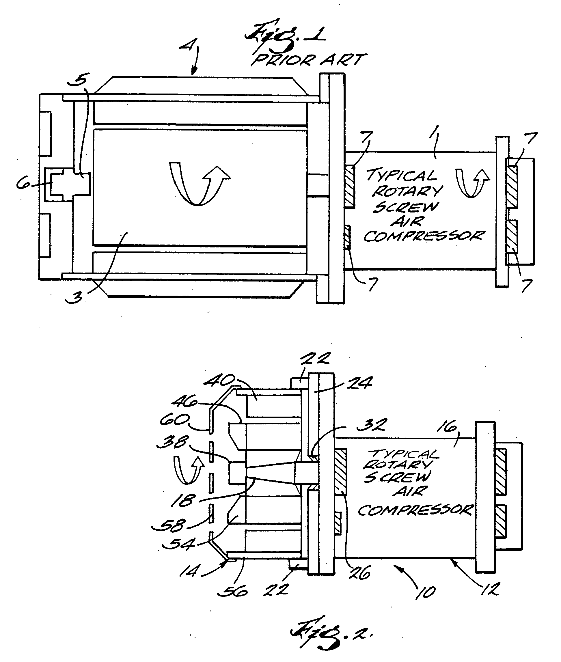
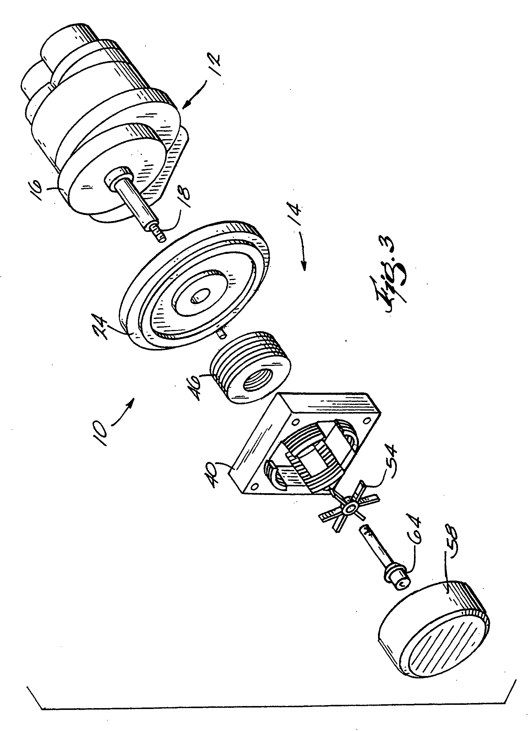
[0027] As shown in FIGS. 2 to 4, the preferred compressor and motor assembly 10 consists of a rotary screw air compressor 12 and a motor 14.

The Rotary Screw Air Compressor 12

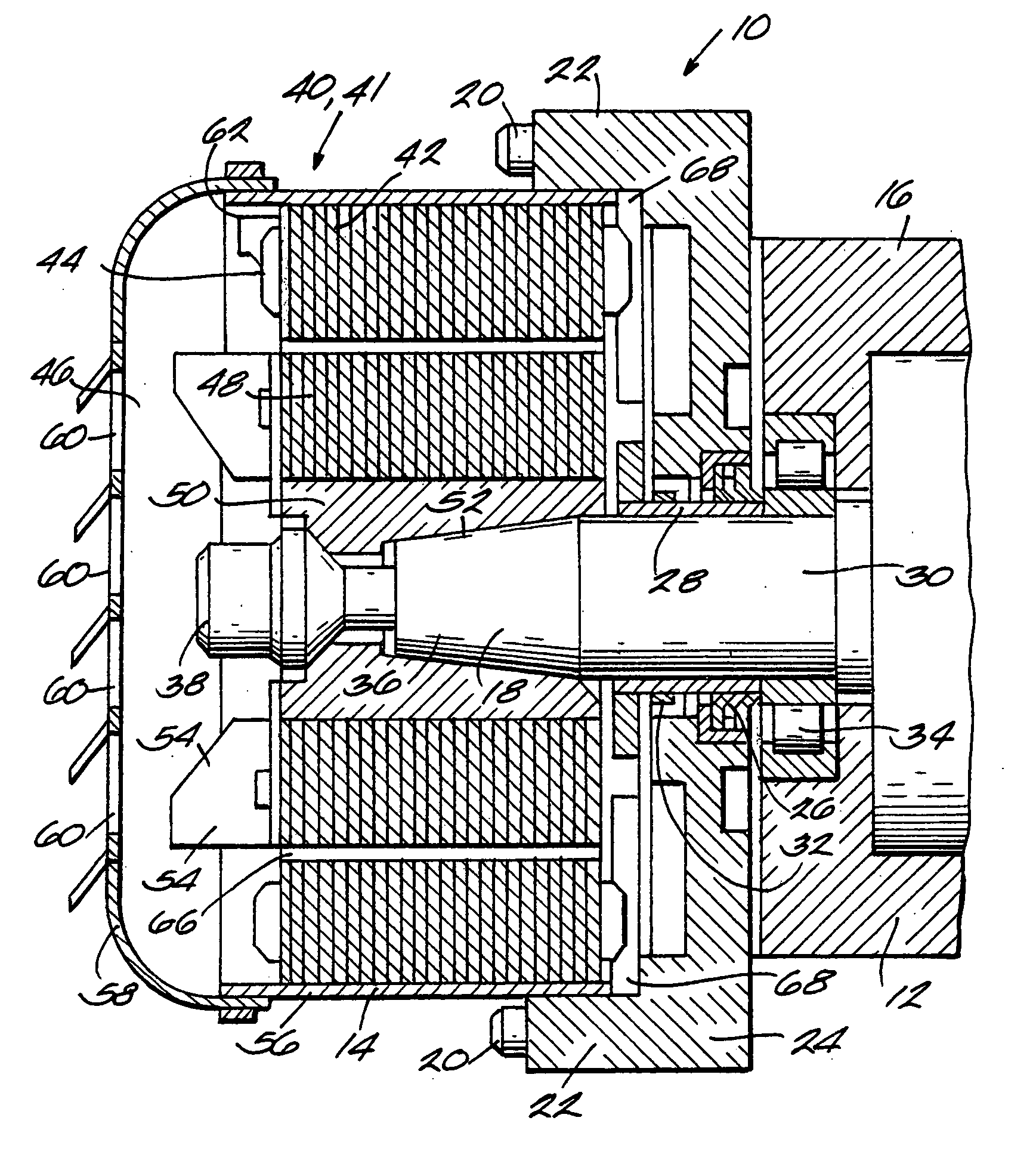
[0028] The rotary screw air compressor 12 (also known as an airend) includes a housing 16 from which extends a shaft 18 (known as an airend input shaft) in use driven to rotate by the motor 14.

[0029] The motor 14 is located by a spigot (not shown) and attached by bolts 20 entered through mounting blocks 22 to an adapter flange 24 of the compressor 12 connected to the housing 16 of compressor 12. The adapter flange 24 includes a main shaft seal 26 configured to cooperate with a shaft seal wear sleeve 28 around a cylindrical portion 30 of the shaft 18. The adapter flange 24 also includes a shaft dust seal 32 which also cooperates with the sleeve 28. The compressor 12 includes an input shaft bearing 34 within its housing 16.

[0030] The shaft 18 has a frustoconical i.e. tapered end portion 36 having a...


PUM


Abstract

In a compressor and driving motor assembly, the driving motor is a hybrid permanent magnet motor and/or has a rotor mounted directly on the drive shaft of the compressor, the drive shaft acting as a cantilever supporting the rotor.

Description

FIELD OF THE INVENTION [0001] The present invention relates to a compressor and driving motor assembly. BACKGROUND OF THE INVENTION [0002] Traditional methods of driving compressors using conventional electric motors include not only direct drive connections, but also intermediate couplings, belts, pulleys and gears. In the simplest known form there is direct drive with the motor rotor joined directly onto the input shaft of a compressor. Such a known compressor and motor assembly is shown in FIG. 1. It includes a rotary screw air compressor 1 having bearings 7, and an extended male input shaft 2 which is connected to the rotor 3 of the motor 4. Even in this simplest form the shear weight of the rotor requires the rotor 3 and input shaft 2 to be supported on additional bearings 5. [0003] Various types of motors are known to be used to drive compressors. For example, fixed speed drive motors known to be used to drive rotary screw air compressors, whether flooded or oil free, have inv...

Claims


Application Information

Patent Timeline
IPC IPC(8): F04B35/04F04B17/00F04C29/00H02K7/14
CPCF04C18/16H02K7/14F04C2240/51F04C29/0085
Inventor COOK, ROGER
Owner INGERSOLL RAND SERVICES LTD
Why Eureka
Try Eureka