Plate and test method using the same

a technology of plate and test method, applied in the field of simple plates, can solve the problems of upset insertion order of test particles, inability to test with high accuracy respective test particles b>3/b>, etc., and achieve the effect of high accuracy

Inactive Publication Date: 2006-03-16
ALPS ALPINE CO LTD
View PDF9 Cites 3 Cited by
  • Summary
  • Abstract
  • Description
  • Claims
  • Application Information

AI Technical Summary

Benefits of technology

[0019] According to an aspect of the present invention, a plate includes a flow path having a concave shape and regulation sections that divide the flow path into a plurality of regions extending an upstream side to a downstream side and regulate the number of test particles to be filled inside the regions.
[0021] Further, in the present invention, the flow path is divided into a plurality of regions by the regulation sections, and the test particles filled in each of the regions can be tested in each of the regions. As such, since a test target region can be previously divided into a plurality of regions, the accumulated tolerances of the test particles in the respective regions are small, even though the test particles filled in the respective regions have tolerances. Therefore, the test particles can be tested with high accuracy inside the respective regions.
[0022] Furthermore, in the above-mentioned structure, it is preferable that the regions be defined between the regulation sections facing each other in a direction intersecting the flow direction of the flow path. Accordingly, a plurality of regions can be provided easily and properly in the flow path.
[0029] As such, whenever the test region is changed, the beginning reference position is also changed. Further, the test particles filled inside the respective regions are tested from a new test beginning reference position, so that the accumulated tolerances of the test particles can be reset in each of the regions, which makes it possible to test the test particles with high accuracy.

Problems solved by technology

Therefore, there is a problem in that the insertion order of the test particles is upset.
As a result, the conventional plate has a problem in that the respective test particles 3 cannot be tested with high accuracy.

Method used


Image

  • Plate and test method using the same
  • Plate and test method using the same
  • Plate and test method using the same

Examples


Embodiment Construction

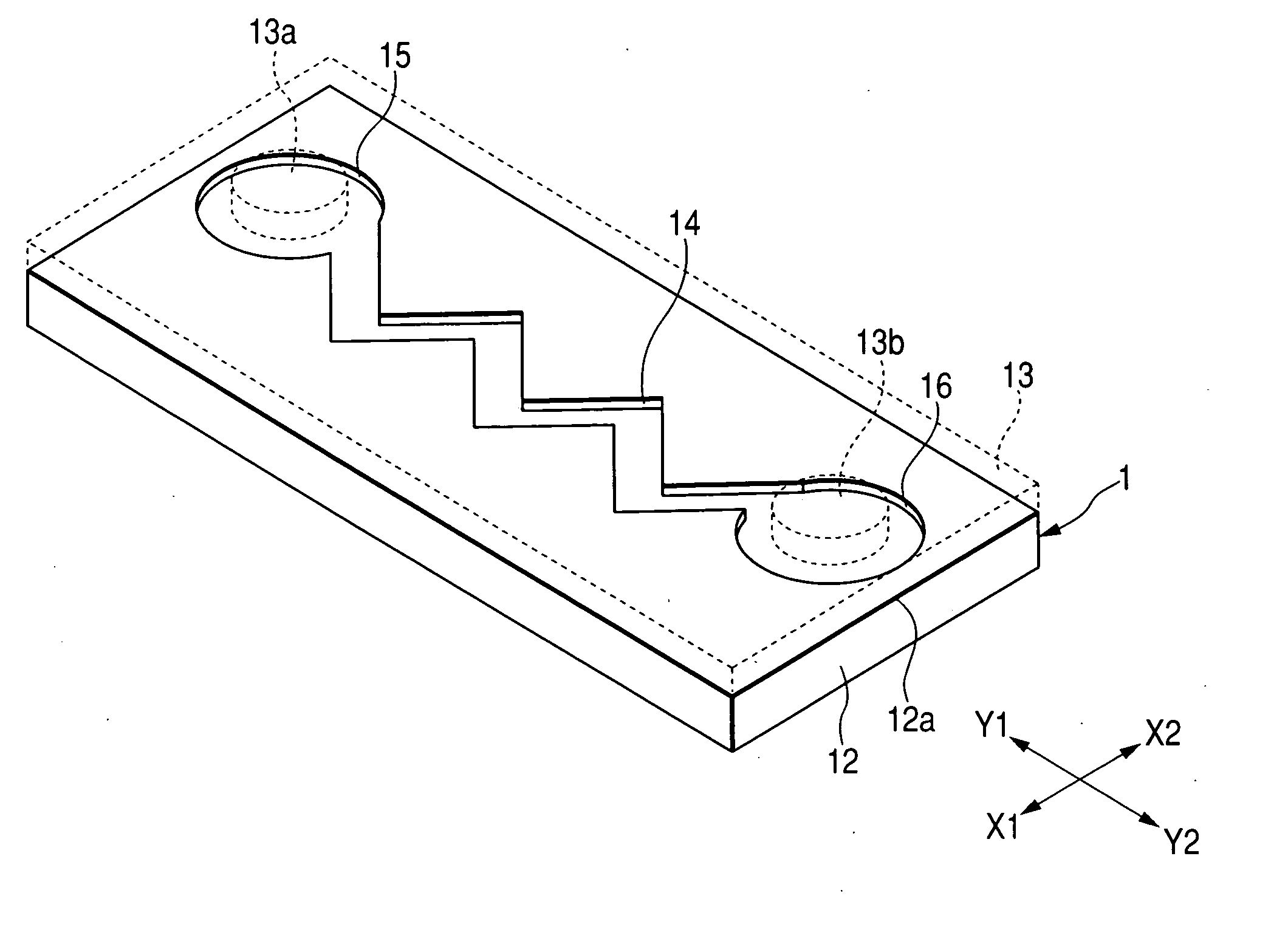
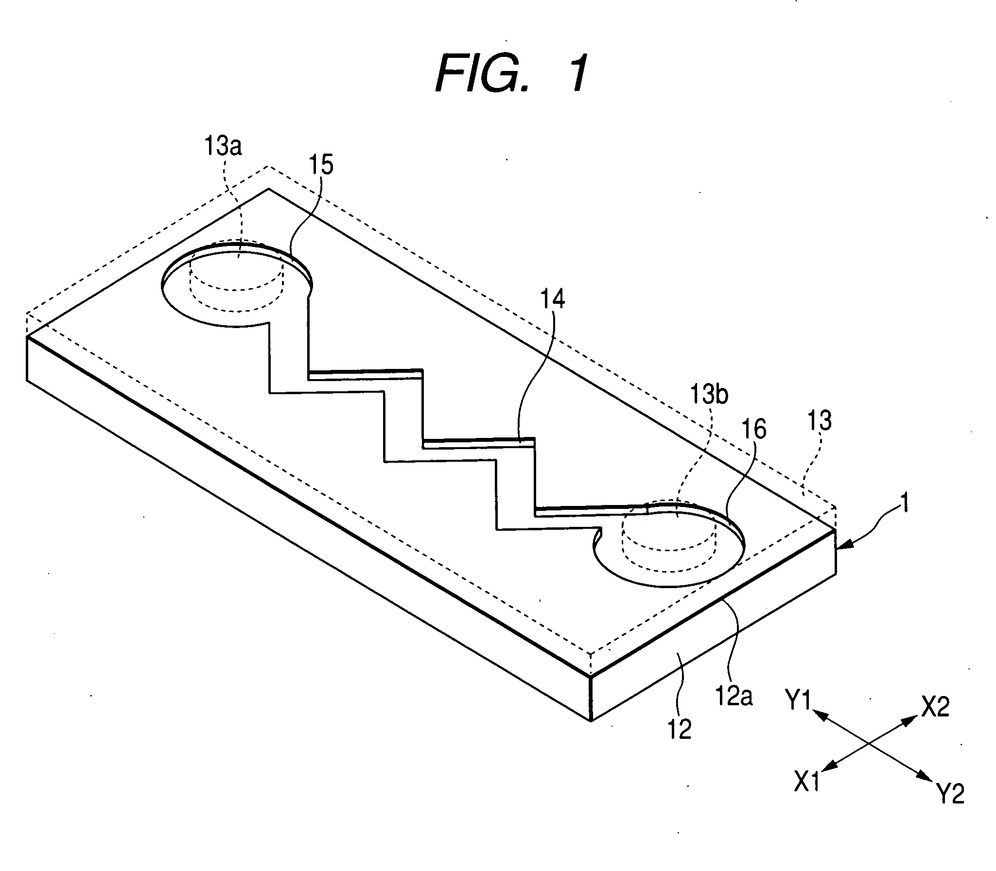
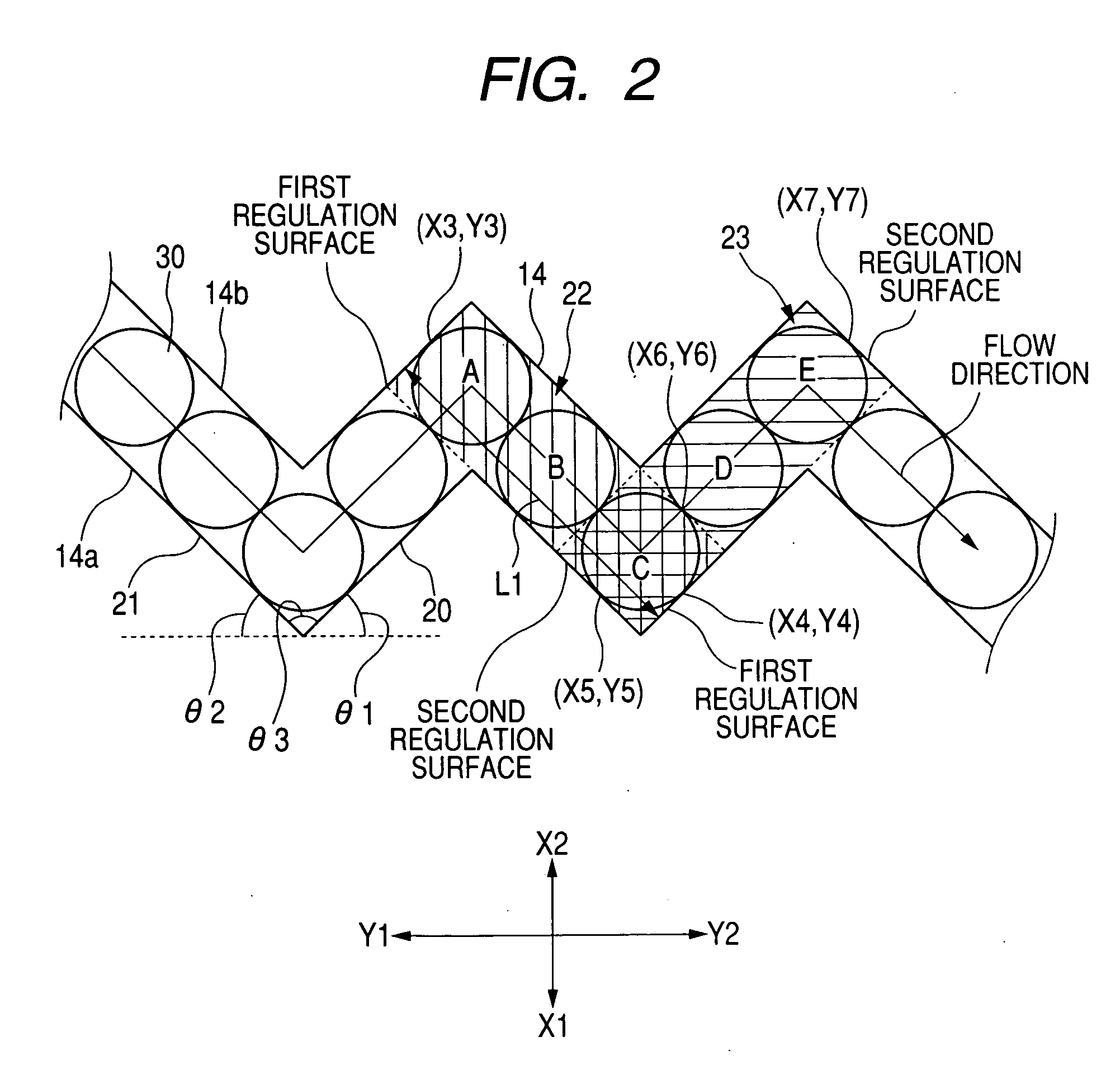
[0038]FIG. 1 is a perspective view illustrating the appearance of a testing plate. FIG. 2 is a partial plan view illustrating the shape of a flow path of the testing plate shown in FIG. 1. FIG. 3 is a perspective view illustrating the appearance of a testing plate having a different shape from the testing plate of FIG. 1. FIG. 4 is a partial plan view illustrating the shape of a flow path of the testing plate shown in FIG. 3. FIG. 5 is a partial plan view illustrating the shape of a flow path of a testing plate having a different shape from the testing plate of FIG. 1. FIG. 6 is a partial plan view illustrating the shape of a flow path of a testing plate having a different shape from the testing plate of FIG. 1. FIG. 7 is a schematic diagram showing an embodiment of a fluorescence detecting device of the present invention.

[0039] A testing plate 1 shown in FIG. 1 performs a predetermined test where a test sample, such as blood or urine collected from the human body, reacts to a pred...


PUM

PropertyMeasurementUnit
diameteraaaaaaaaaa
inclination angles θ1aaaaaaaaaa

Abstract

A flow path is formed in a zigzag shape to have a predetermined width from an upstream side to a downstream side. Accordingly, both side surfaces of the flow path divide the flow path into a plurality of regions from the upstream side to the downstream side to function as regulation surfaces for regulating the number of test particles filled inside the regions. Further, when a test is performed on each of the regions, the accumulated amount of tolerances of the test particles in the respective regions is small, which makes it possible to test the test particles with high accuracy.

Description

BACKGROUND OF THE INVENTION [0001] 1. Field of the Invention [0002] The present invention relates to a simple plate capable of performing a blood test, a urine test, and a DNA test by a medical institution or an individual, and more specifically, to a plate and a test method using the same capable of performing a test on test particles filled inside a flow path with high accuracy. [0003] 2. Description of the Related Art [0004] Recently, a testing chip for a collected material from the human body, such as blood or urine, has been increasingly developed. For example, a DNA chip where multiple kinds of DNA fragments (referred to as probes or reagents) are attached on a substrate made of, for example, glass can detect plural kinds of specific genes (for example, cancer gene) from genes (referred to as a test sample or target) collected from the human body at one time. [0005] When the detection of biological molecules, which has been conventionally performed by a test tube, a dropper, a...

Claims


Application Information

Patent Timeline
Patent Type & Authority Applications(United States)
IPC IPC(8): C12M1/34
CPCB01J2219/00466B01J2219/005B01J2219/00657B01J2219/00702B01L3/5027B01L2200/0647G01N33/558B01L2300/0636B01L2300/0822B01L2300/0825B01L2400/0457G01N15/1484B01L2200/12
Inventor YAMASHITA, TATSUMAROTAKAMURA, SHOZOSHIBUYA, YOSHIHISA
Owner ALPS ALPINE CO LTD
Why Eureka
Try Eureka