Method and system for testing a control system of a marine vessel

a control system and marine technology, applied in the direction of testing/monitoring control systems, vessel construction, instruments, etc., can solve problems such as hidden physical dangers, difficulty in inspection by inspectors, and errors

Inactive Publication Date: 2006-03-16
MARINE CYBERNETICS
View PDF37 Cites 70 Cited by
  • Summary
  • Abstract
  • Description
  • Claims
  • Application Information

AI Technical Summary

Benefits of technology

[0038] storing said control system's (2) response (S0) to said first test sequence (T0) at said first time (t0) as said control system's (2) “signature” response (S0);

Problems solved by technology

However, to make an entirely realistic test of the vessel in conditions that are to be expected, it would be necessary to wait for or to seek weather situations and sea states that are expected, but rarely occur, or to wait for or to provoke situations that could be expected if certain errors occurred, but that would be dangerous if such situations occurred accidentally or by provocation.
Such interconnecting and testing could be conducted on the vessel, but a disadvantage of visiting the vessel to be tested is often related to a long way of travel for the ship inspector, that the ship inspector must bring equipment for interconnection to the control system inputs for measurements, and equipment for interconnection to the control system outputs for response in the form of control signals that are normally sent to the actuators of the vessel, and in addition a data library that at least has to include the configuration of the actual vessel to be tested.
Moreover, the travel time from one vessel that is to be tested and certified to a next vessel can make it difficult for the inspector to perform inspections at a sufficiently high rate, so that the next vessel will have to wait, with the economic disadvantages caused by the waiting, if the vessel cannot be taken into use without being tested and properly certified.
It may also cause a concealed physical danger to use a vessel where lack of testing of the control system does not reveal possible errors.
This type of FAT can only reveal errors where measurements from sources that the manufacturer has foreseen to exist, and where the control signals are only related equipment that the manufacturer have foreseen.
Thus, it will not be known with certainty how the control system will interact with equipment, systems, configurations or situations that the manufacturer of the control system has not foreseen.
In addition, in a FAT the control system will not be tested in the connection where the control system is installed and connected for use on the vessel.
The vessel may experience loss of motor power for one or more propellers or rudders, and have to increase the motor power on the remaining propellers and / or thrusters and perhaps rotate the still functioning remaining rudders or thrusters.
One may also experience serious error situations in which the control system loses some of the signals from the connected sensors so that an undesired incident may occur.
Such an error may be called a “step change” error.
However, it turned out that after 5 minutes the drilling platform suddenly started to move off towards the desired position according to the then erroneous DGPS signals.
Such a situation may involve a risk for blow-out of gas and oil, or pollution by spilling of drilling fluid.
Such a situation may also present a risk to the vessel and the crew.
After a discontinued DP-drilling it may be very expensive to recover continued drilling.
The applicants assume that the initial sudden change of the position calculated by the DGPS receivers may have been caused by disturbances in the signal transmission from the GPS satellites to the receivers, or by a situation of having an insufficient number of available satellites.
At present, satisfactory test equipment and procedures are not available for the testing of the control systems on a vessel after such changes.
In contrast to this there are no established systems or methods for the testing of the software of the crane control systems.

Method used


Image

  • Method and system for testing a control system of a marine vessel
  • Method and system for testing a control system of a marine vessel
  • Method and system for testing a control system of a marine vessel

Examples


Embodiment Construction

1.1 Description of the Vessel and Control System, General.

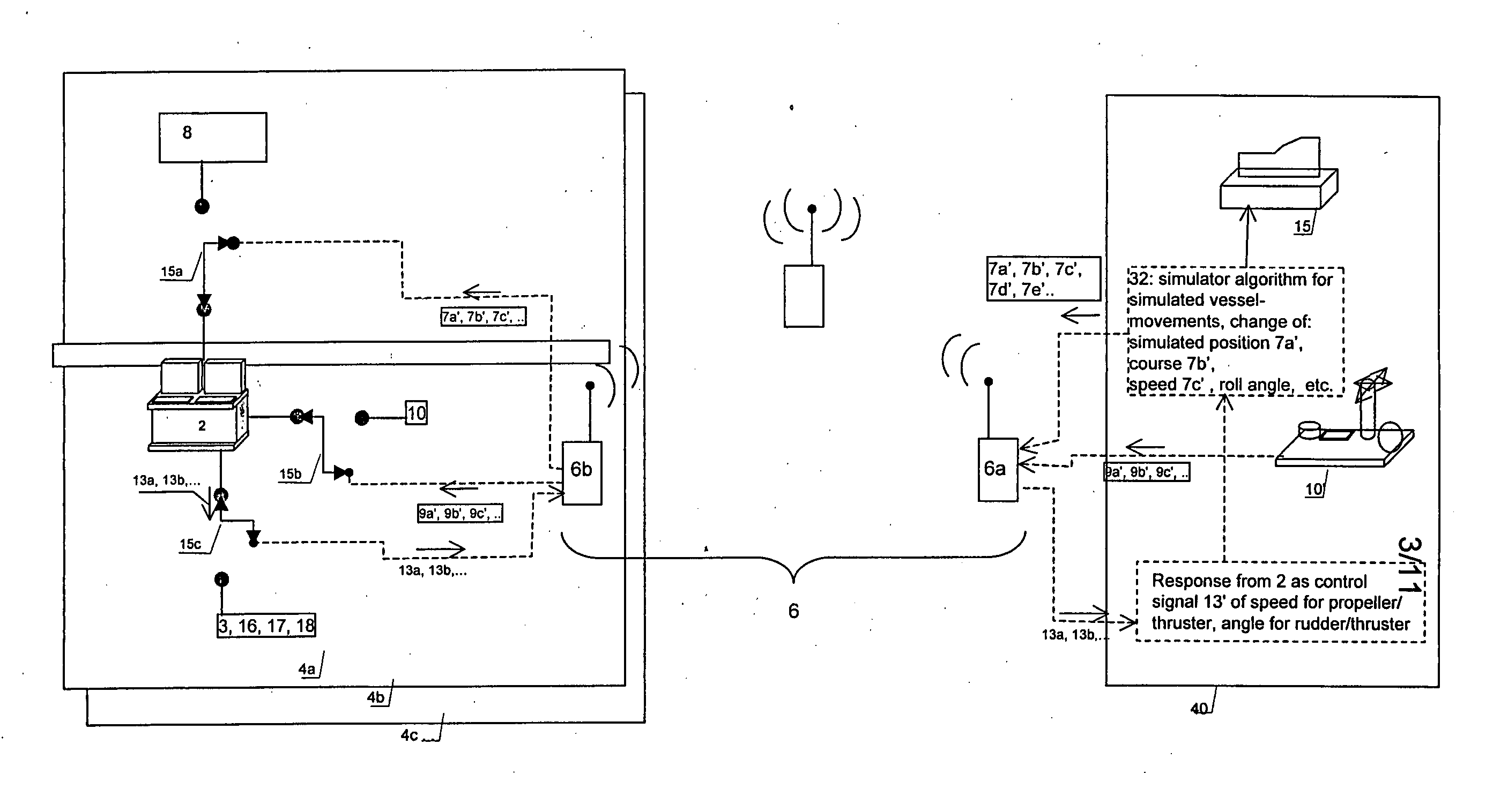
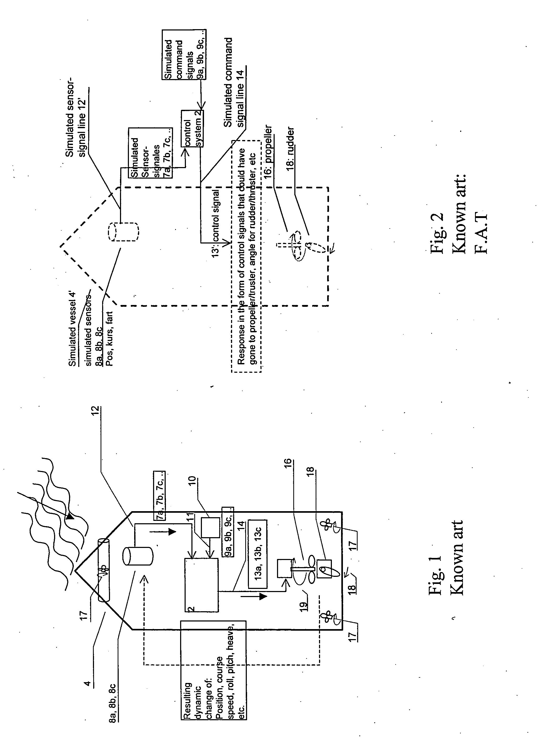
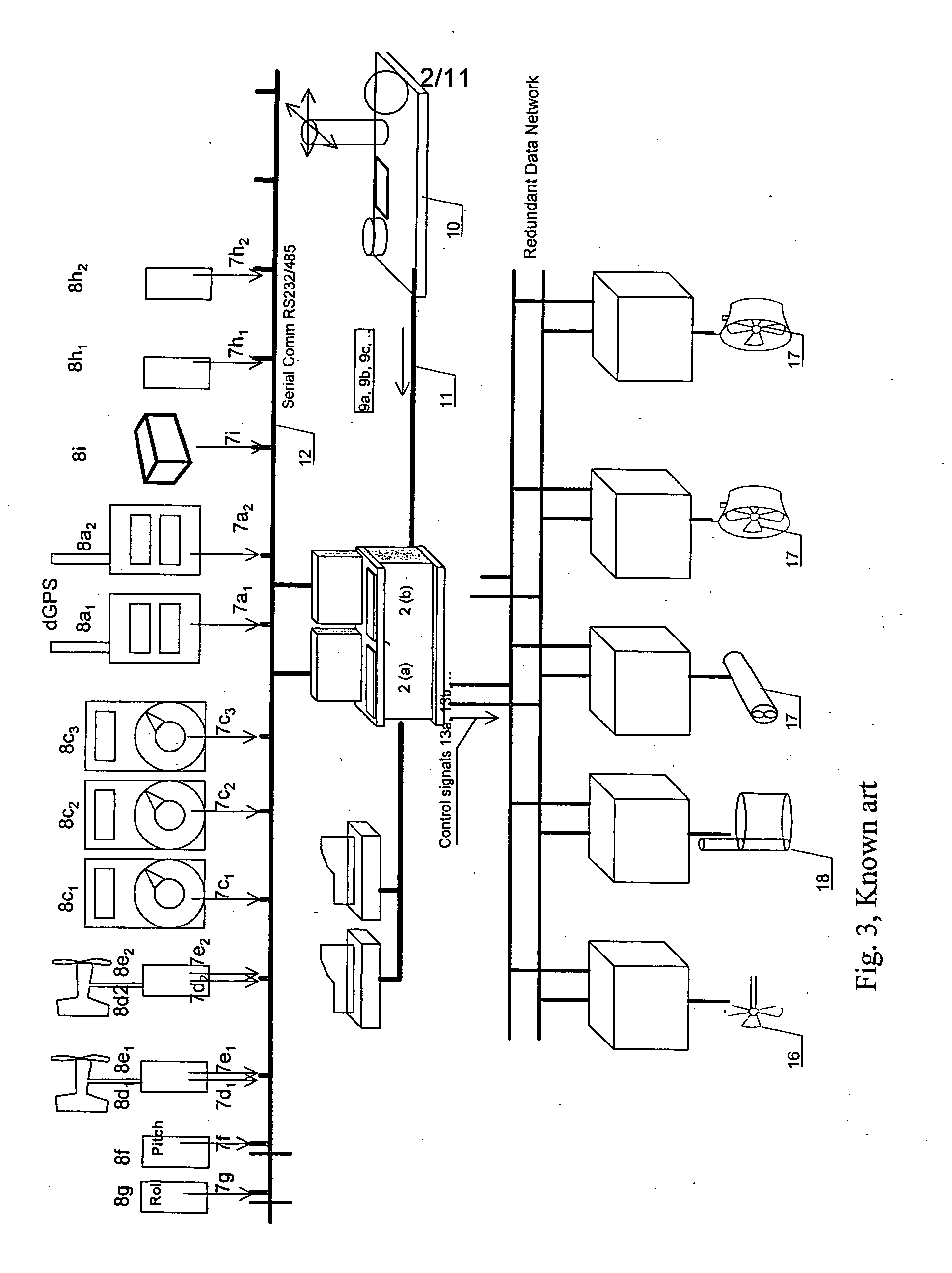
[0057] The invention will now be described with reference to some embodiments of the invention illustrated in the drawings enclosed. The invention includes a system for and a method for testing of a control system (2) on a vessel (4), e.g. a ship, a drilling platform, a petroleum production platform, in real time over a communication channel (6), as shown in an overview in FIG. 4a and in more detail in FIGS. 4b and 4c. The control system (2) may include control and monitoring of the vessel (4). Testing of the control system (2) may include the simulation of normal states and extreme states and normal changes to such normal and extreme states for the vessel (4), for example ordinary movement in a simulated calm sea state (H1). In addition, one may simulate ordinary movement in a simulated extreme sea state (H2), failure situations with e.g. loss of motor power on a single propeller (16) where the vessel has only this single ...


PUM


Abstract

A method for verifying a control system (2) of a vessel (4), in which said control system (2) in its operative state receives sensor signals (7) from sensors (8) and command signals (9) from command input devices (10), and as a response provides control signals (13) to actuators (3) in order to maintain a desired position, velocity, course or other state of said vessel (4), characterized by the following steps:
    • during a time (t0), disconnecting the reception of real sensor signals (7a, 7b, 7c, . . . ) and replacing said real sensor signals by a test sequence (T0) of artificial measurements (7a′, 7b′, 7c′, . . . ) from a test signal source (41);
    • letting said control system (2) work based on the artificial sensor signals (7, 7′) to generate control signals (13′) to be recorded as a response (S0) to said first test sequence (T0) for said first time (t0) on a control signal logger (42) and storing response (S0) to the test sequence (T0) as the control system's (2) “signature” response (S0);
said method having the purpose of, at a later time (t1, t2, t3, . . . ), to use the test sequence (T0) input to the control system (2), and record a later response (S1, S2, S3, . . . ) and determining whether said later response similar to the signature response (S0) to verify that said control system (2) is unchanged, or not.

Description

[0001] The present invention relates to a system for acquiring a verifiable control system signature after approval of a marine vessel by testing and / or certification by a class society. Further the invention relates to remote testing of a vessel, and a combination of the two methods, i.e. remote acquisition of a control system signature. Further, a system for remotely controlled testing and vessel simulation is provided. [0002] A control system can generally be seen as a system that provides control signals to a physical process, and that receives measurements from a device or a physical process or possibly from other physical processes. The measurements and an algorithm are used to compute the control signals so that the physical system responds as desired. If the physical process is a motorized vessel, then the control system may receive measurements in the form of a vessel position, course and velocity, and can thereby calculate the control signals to propellers and rudders so t...

Claims


Application Information

Patent Timeline
Patent Type & Authority Applications(United States)
IPC IPC(8): G06F17/00G01D1/02G05B13/04G05B23/02
CPCG05B23/0256B63B71/00G05D1/0206B63H25/00G05B23/02G05D1/02
Inventor FOSSEN, THOR INGESORENSEN, ASGEIR JOHANEGELAND, OLAVJOHANSEN, TOR ARNE
Owner MARINE CYBERNETICS
Why Eureka
Try Eureka