
Architecture with shared memory

a technology of shared memory and architecture, applied in the field of integrated circuits, to achieve the effect of reducing memory latency

Inactive Publication Date: 2006-03-16
FRENZEL RUDI +4
View PDF3 Cites 6 Cited by
  • Summary
  • Abstract
  • Description
  • Claims
  • Application Information

AI Technical Summary

Benefits of technology

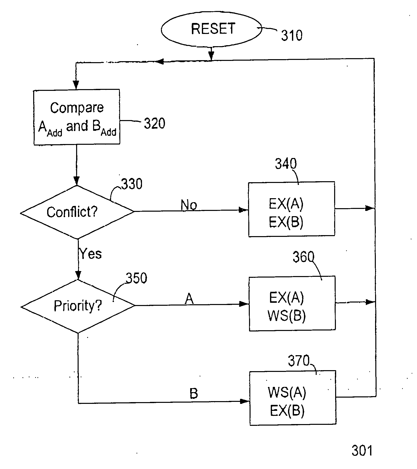
[0005] The invention relates, in one embodiment, to a method of sharing a memory module between a plurality of processors. The memory module is divided into n banks, where n=at least 2. Each bank can be accessed by one or more processors at any one time. The memory module is mapped to allocate sequential addresses to alternate banks of the memory, where sequential data are stored in alternate banks due to the mapping of the memory. In one embodiment, the memory banks are divided into x blocks, where x=at least 1, wherein each block can be accessed by one of the plurality of processors at any one time. In another embodiment, the method further includes synchronizing the processors to access different blocks at any one time. In another embodiment, first and second signal paths are provided between the memory module and a processor. The first signal path couples a cache to a processor and memory module for enabling the processor to fetch a plurality of data words from different banks simultaneously. This reduces memory latency caused by memory contention. The second signal path couples the memory module directly to the processor.

Problems solved by technology

However, the improved performance is achieved at the sacrifice of chip size since duplicate memory modules are required for each processor.

Method used


Image

  • Architecture with shared memory
  • Architecture with shared memory
  • Architecture with shared memory

Examples


Embodiment Construction

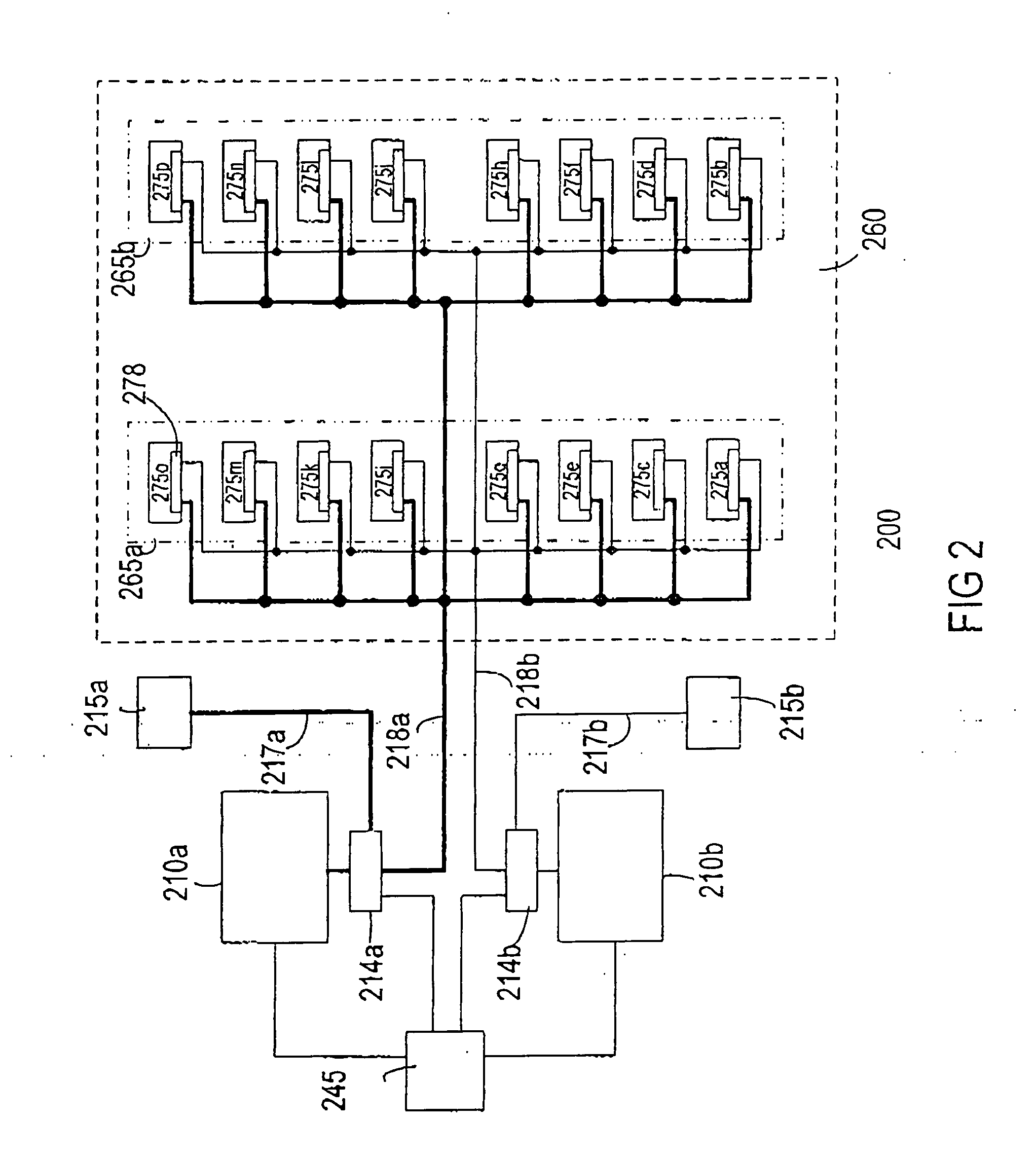
[0012]FIG. 2 shows a block diagram of a portion of a system 200 in accordance with one embodiment of the invention. The system comprises, for example, multiple digital signal processors (DSPs) for multi-port digital subscriber line (DSL) applications on a single chip. The system comprises m processors 230, where m is a whole number equal to or greater than 2. Illustratively, the system comprises first and second processors 210a-b (m=2). Providing more than two processors in the system is also useful.

[0013] The processors are coupled to a memory module 260 via respective memory buses 218a and 218b. The memory bus, for example, is 16 bits wide. Other size buses can also be used, depending on the width of each data byte. Data bytes accessed by the processors are stored in the memory module, to in one embodiment, the data bytes comprise program instructions, whereby the processors fetch instructions from the memory module for execution.

[0014] In accordance with one embodiment of the i...


PUM


Abstract

A system with multiple processors sharing a single memory module without noticeable performance degradation is described. The memory module is divided into n independently addressable banks, where n is at least 2 and mapped such that sequential addresses are rotated between the banks. Such a mapping causes sequential data bytes to be stored in alternate banks. Each bank may be further divided into a plurality of blocks. By staggering or synchronizing the processors to execute the computer program such that each processor access a different block during the same cycle, the processors can access the memory simultaneously. Additionally, a cache is provided to enable a processor to fetch from memory a plurality of data words from different memory banks to reduce memory latency caused by memory contention.

Description

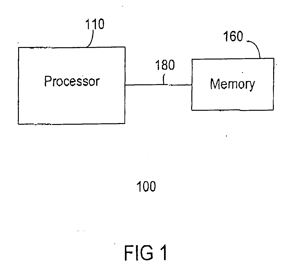
FIELD OF THE INVENTION [0001] The present invention relates generally to integrated circuits (ICs). More particularly, the invention relates to an improved architecture with shared memory BACKGROUND OF THE INVENTION [0002]FIG. 1 shows a block diagram of a portion of a conventional System-on-Chip (SOC) 100, such as a digital signal processor (DSP). As shown, The SOC includes a processor 110 coupled to a memory module 160 via a bus 180. She memory module stores a computer program comprising a sequence of instructions. During operation of the SOC, the processor retrieves and executes the computer instructions from memory to perform the desired function. [0003] An SOC may be provided with multiple processors that execute, for example, the same program. Depending on the application, the processors can execute different programs or share the same program. Generally, each processor is associated with its own memory module to improve performance because a memory module can only be accessed ...

Claims


Application Information

Patent Timeline
Patent Type & Authority Applications(United States)
IPC IPC(8): G06F13/00G06F9/46G06F12/06
CPCG06F13/1652G06F12/0607G06F12/00
Inventor FRENZEL, RUDIHORAK, CHRISTIANTERSCHLUSE, MARKUSUHLEMANN, STEFANJAIN, RAJ KUMAR
Owner FRENZEL RUDI
Learn More