Hydraulic traction system for vehicles

a technology of hydraulic traction system and vehicle, which is applied in the direction of engine lubrication, steering gear, rotary piston engine, etc., can solve the problems of inefficiency of conventional vane-based hydraulic motor, and achieve the effect of reducing the displacement angle of the chamber and reducing the volume of the chamber swep

Inactive Publication Date: 2006-03-23
SHEVKET ALPER
View PDF5 Cites 18 Cited by
  • Summary
  • Abstract
  • Description
  • Claims
  • Application Information

AI Technical Summary

Benefits of technology

[0006] The present invention provides a hydraulic traction system for vehicles. In a preferred embodiment, the system comprises a hydraulic vane motor mounted at each wheel of the vehicle (herein after wheel motors), and equal number of identical units installed as engine driven pumps for volumetric sufficiency without excess flow while cruising; and a control system for regulating the flow and direction of hydraulic oil during operation. It is desirable to have an efficient hydraulic wheel motor to provide the power to the wheels. The present invention provides a hydraulic motor in which the incoming hydraulic oil (sometimes referred

Problems solved by technology

However, while a vehicle of this type has been used in slower moving farm or off road vehicles, various challenges exist to provide a mainstream hydra

Method used


Image

  • Hydraulic traction system for vehicles
  • Hydraulic traction system for vehicles
  • Hydraulic traction system for vehicles

Examples


Embodiment Construction

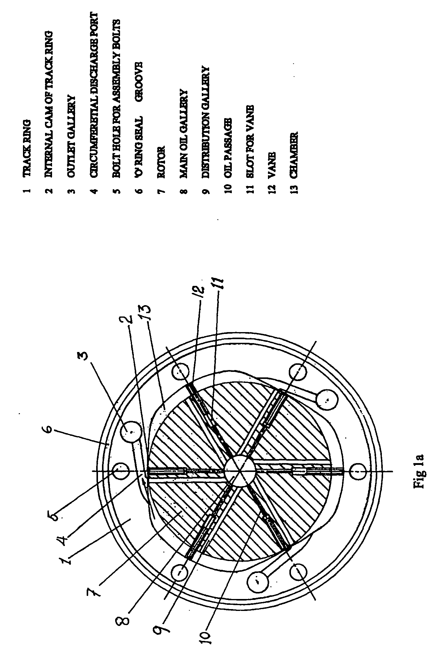
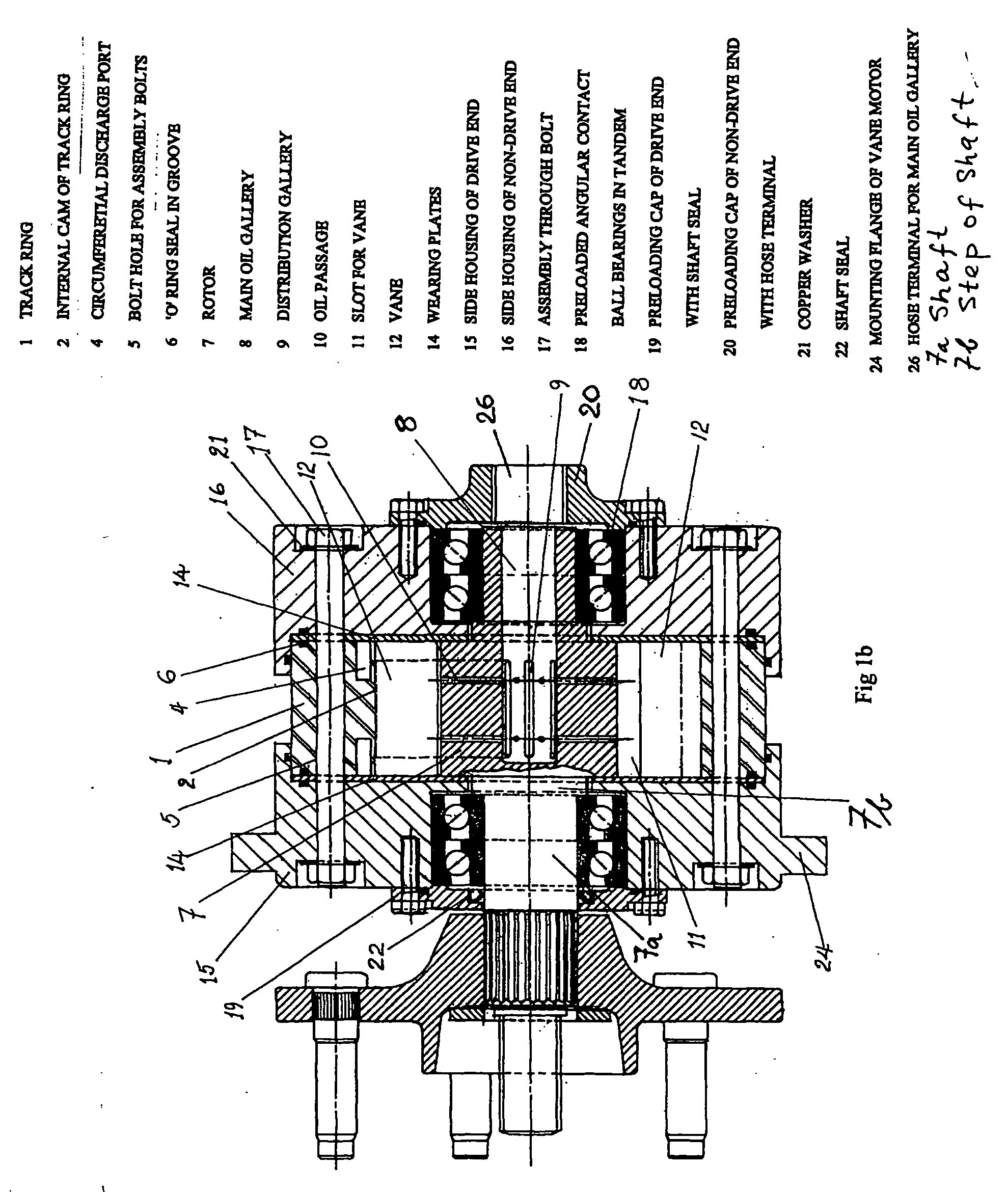
[0020] Referring now to FIGS. 1A, 1B and 1C, the hydraulic motor of the present invention will now be described. The hydraulic motor is composed of a track ring 1. The track ring 1 has three internal cams 2, three outlet galleries 3, and three pairs of discharge ports 4, which discharge into the outlet galleries 3. The three pairs of discharge ports 4, are machined on both faces of track ring 1. Also o-ring seal groove 6, is machined on both faces of track ring 1. Track ring 1 has six bolt holes 5, for the assembly through bolt 17.

[0021] The unit has a rotor 7, which is a single component comprising both rotor 7 and a shaft 7a. The rotor 7 has a main oil gallery 8, extending from the non-drive end of the shaft to beyond the center of the rotor 7 far enough to feed the flow of high pressure hydraulic oil to the distribution galleries 9, of the rotor 7, and the oil passages 10, of the rotor 7. Rotor 7 also has six slots 11 for vanes and a free moving vane 12 in each slot. The shaft 7...


PUM


Abstract

A hydraulic traction system for vehicles is described. The system comprises a hydraulic vane motor mounted at each wheel of the vehicle, and equal number of identical hydraulic vane motors operated as engine driven pumps, and a control system for regulating the flow and direction of hydraulic oil during operation. The hydraulic motor is of a novel design that has a hollow non-drive shaft that accepts incoming hydraulic oil, this allows internal components of the hydraulic motor to be arranged in such a way to improve the efficiency of the hydraulic traction system.

Description

FIELD OF INVENTION [0001] This invention relates to land vehicles, and more particularly to vehicles utilizing hydraulic drive motors to drive the wheels. BACKGROUND OF INVENTION [0002] Hydraulic wheel motors have been used on various automotive and non-automotive types of vehicles. In particular, hydraulically driven vehicles have achieved a fair degree of commercial success in farm vehicles. [0003] These hydraulic wheel motors are provided with a rotary member and a stationary member having a plurality of cavities for pumping hydraulic oil which periodically varies in displacement as the stationary and the rotary member move relative to one another. Hydraulic oil from an engine driven pump is supplied to the hydraulic wheel motors for propelling the vehicle. [0004] A vehicle that is solely driven by hydraulics has the advantage of eliminating mechanical drive train components such as a conventional transmission, clutches, and driveshaft. However, while a vehicle of this type has b...

Claims


Application Information

Patent Timeline
IPC IPC(8): F16D31/00
CPCB60K7/0015B60K17/30B60K2007/0038F16D31/06F04C2/3446F04C2240/603B60K2007/0092
Inventor SHEVKET, ALPER
Owner SHEVKET ALPER
Why Eureka
Try Eureka